Since collaborative robots burst onto the scene some 20 years ago, they have transformed assembly lines and made automation more accessible to smaller manufacturers.
But, there are trade-offs to consider between the economic and ergonomic benefits of cobots and the speed, precision and inherent flexibility of people.
This was the crux of an automated assembly application that an Italian OEM recently brought to the i-Labs Industry Laboratory in Jesi, Italy. Founded in February 2022, i-Labs is a nonprofit design and engineering consortium consisting of Marche Polytechnic University; the University of Camerino; Meccano, an engineering firm; Cadland, a design software reseller; Gruppo Fillipetti, a technology consulting firm; Joytek, a systems integrator; and Naut@s, a digital design firm.
The OEM wanted to automate assembly of a subcomponent for a larger product. Assembly of the subcomponent was initially performed manually. Although the operations were straightforward, they consisted of repetitive tasks that were not considered value-adding by the manufacturer. Nevertheless, they were essential for completion of the product.

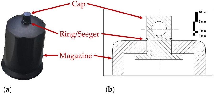
An OEM wanted to automate assembly of a subcomponent for a larger product. The image on the left shows the assembled component. The image on the right is a simplified cross-section to show the location of the parts. Source: Marche Polytechnic University
The sequence of operations to assemble the subcomponent is as follows:

This diagram shows the sequence of steps in the automated assembly process. Source: Marche Polytechnic University
- Pick and place a cap.
- Pick and place a magazine.
- Pick and place a cone (a reusable tool for inserting a ring into a housing)
- Pick and place the ring.
- Insert the ring into its seat.
- Remove the cone from the assembly and reposition it on its base.
The cone is instrumental to the assembly process. It is used to guide insertion of the ring into the housing. The cone facilitates the elastic deformation of the ring as it is pressed towards the wider part of the cone. This process causes the ring to expand and conform to the dimensions of the housing. Upon insertion, the ring attempts to return to its original size, thereby securing the cap to the magazine through a clamping action.
Our design process for the project followed a trial-and-error approach, testing various CAD models and setups. The design process consisted of the following steps:
- Understand the customer’s requirements.
- Determine what tasks could be executed solely by the robot and which need traditional automation.
- Identify the various tasks and figuring out their execution.
- Test and evaluate the functionality of each automation idea.
- Use the results to modify the ideas, a process that was greatly aided by additive manufacturing.
- Repeat the process until a satisfactory system is achieved.
Ultimately, we designed two distinct systems: a corporate one and a research-focused one. The system detailed in this paper is different from the one that was actually implemented by the OEM. The OEM did not fund our research-focused system. It was developed solely to explore new methodologies in the application of cobots.
Looking for a reprint of this article?
From high-res PDFs to custom plaques, order your copy today!
The research-focused system consisted of a FANUC CRX 10iA/L collaborative robot. The cobot was equipped with a SCHUNK Co-act EGP-C gripper—an electric, two-finger, parallel gripper designed for collaborative operations and versatility in handling small parts.
To assist with production of fixtures and tooling, we used a Formlabs 3 SLA 3D printer. Employing laser technology for resin curing, the Formlabs 3 ensures high precision and detail, though it comes with limitations, such as slower print speeds and additional post-processing. Siemens NX software was used for creating CAD models, which were subsequently exported in STL format to the Formlabs printer.
The setup of our research-focused system was straightforward. The components (magazine, cap, ring and cone) are arranged in a line. Nearby are a ring holder and assembly support. The entire assembly process is carried out directly on this support.

This series of photos shows automated assembly sequence: (a) positioning of the cap, (b) positioning of the magazine, (c) gripping of the guiding cone by the robot, (d) detail of the approach position for gripping the ring, (e) close-up view of the ring correctly gripped by the robot, (f) positioning stage of the ring in preparation for insertion, (g) insertion of the ring into its housing assisted by the cone, and (h) removal of the cone after assembly. Source: Marche Polytechnic University
Programming of the robot was carried out using FANUC’s teach pendant, which is known for its relative simplicity. Specifically, it allowed for precise fine-tuning, a critical feature for this project. This meant that we could approximate the robot’s positioning and orientation and then make exact adjustments as needed, enhancing the accuracy and effectiveness of the robot’s operations in the assembly process. This capability proved essential in achieving the desired precision in the assembly tasks.
Design of the Fingers
The gripper fingers were designed to perform multiple tasks within a single setup. Developed using Siemens NX, the designs were exported in STL format for printing with the Formlabs 3 SLA printer. The fingers were printed using gray resin.
| Component | Shape and Function | Special Features |
|---|---|---|
| Magazine grip | Irregular cylindrical, decagonal shape | Adaptable to various positions |
| Cap grip | Cylindrical with linear geometry | Ensures secure and universal grip |
| Cone grip | Negative form, narrow at base | Prevents CONE from being pushed out |
| Ring grip | Triangular and elliptical internal space | Selects and grips small rings |
The gripper fingers were designed to perform the following tasks:
- Magazine grip. The magazine has an irregular cylindrical shape. The adoption of a decagonal shape for the grip interface has shown practical effectiveness, as its geometry increases the contact points. This design advantage was observed through empirical testing, where the decagonal grip consistently accommodated various placements of the magazine, resulting in stable and secure handling without the need for precise positioning.
- Cap grip. The cap grip uses a similar principle to the magazine grip. With the cylindrical shape of cap, a linear geometry aids in ensuring a more secure and universal grip.
- Cone grip. The cone grip is designed for interference with a negative form fit. To ensure a firm grip on the cone and prevent it from being pushed outward, the negative form is designed narrower at the base and wider towards the top. Forces at play tend to push the cap upwards, which is then blocked by form interference. This part of the fingers also serves to push the ring into its final seat. Being narrower at the base ensures that the ring does not get trapped inside the cap.
- Ring grip. This component is the most critical, because it’s so small (outer diameter of 9 millimeters and thickness of about 0.7 millimeter). This makes it difficult to grip. To make them easier to grip, the rings are inserted onto a special holder, lined up one above the other. The open gripper is brought into position over the holder and then closed. The lower triangular geometry of the gripper selects only one ring, and the inner space of the housing allows only one ring to enter. Furthermore, the internal space is elliptical, not circular, to accommodate the ring and allow for slight deformation. The ring is then transported and inserted into the upper part of the cone, already positioned over the previously assembled component. The ring is released and, with the seat of the cone, is pushed into its final position.
Normally, no more than 3 kilograms of force is necessary to seat the ring, but various types of friction can increase the force to unacceptable levels. Additionally, during this phase, the cap and the gripper must be vertically aligned, since misalignments can lead to an increase in insertion force that could exceed the robot’s 10-kilogram payload or even break the gripper. This could be avoided through force-control technology.

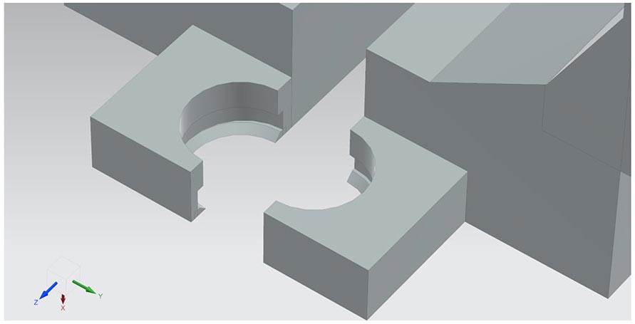
The gripper fingers were designed to perform multiple tasks. The left images shows a top-down perspective, highlighting the central decagonal hole for gripping the magazine. The right image shows the hole for the cap and a conical hole for gripping the cone. Source: Marche Polytechnic University
Cycle Time
The manual assembly process normally takes about 15 seconds. In contrast, the robotic operation takes 50 seconds, which is longer due to the serialized nature of the tasks. However, the robotic system offers significant advantages, such as enabling continuous assembly outside of regular working hours or with fewer staff. This allows operators to focus on more critical and value-adding tasks.
This study underscores that, while the task could technically be executed entirely by a cobot, it is not recommended due to the complexity of tasks such as gripping and inserting small rings. The sensitivity and malleability of human hands are much better at the task, and it’s challenging to replicate those traits with current robotic technology. Further research is needed to develop a more reliable process for gripping small rings.

The image illustrates the feature of the gripper that enables it to pick and place one small ring from a pile of rings arranged one above the other. Source: Marche Polytechnic University
The key conclusions of our study are as follows:
- Shifting from manual to robotic assembly in this application is feasible, but not advisable. Engineers are well-advised to design products with robotic assembly in mind, incorporating specific features that simplify robot programming and facilitate easier assembly by robots.
- Slower operational speeds are crucial for maintaining precision in robotic assembly, particularly due to vibrations caused by the robot’s motors.
- A short pause, prior to assembly of each component, is essential to minimize vibration of the robot arm and enhance repeatability of the operation.
For more information on cobots, read these articles:
Cobot Welder Transforms Small Business
The Effect of Cobots on Worker Productivity
Collaborative Robot Do’s and Don’ts


.jpg?height=300&t=1733742897&width=300)


