Join Sheet Metal With Cold-Extruded Pins

Photo: scibak / iStock / Getty Images Plus
Lightweight structures and multi-material assemblies are of great interest to the automotive industry. However, joining dissimilar materials poses a challenge. Conventional joining methods, such as welding, bonding, screwdriving and riveting, have limited effectiveness due to differences in stiffness, chemical compatibility and thermal expansion.
A new mechanical joining method, using pin structures formed in one of the parts, has shown promise for assembling dissimilar materials. With this method, no additional elements, such as rivets and screws, are necessary to join the components, which saves weight.
Considerable research has been done on joining fiber-reinforced plastics (FRP) to sheet metal using pins. In one study, for example, fiberglass fabric was placed on top of pins formed in sheet metal. Polyester resin was then vacuum-infused into the fabric, creating an assembly with the pins locked and bonded within the FRP.
Pins also show great potential for joining dissimilar metals, such as steel and aluminum. For example, one study demonstrated the suitability of using pins to join DC04 steel with AA6016-T4 aluminum alloy. Cylindrical pins, 1.32 millimeters in diameter, were cold-formed in the steel part, which was then pressed directly into a sheet of unperforated aluminum, creating an undercut by upsetting the pin within the joining partner. The assembly produced a shear strength of 363 newtons.
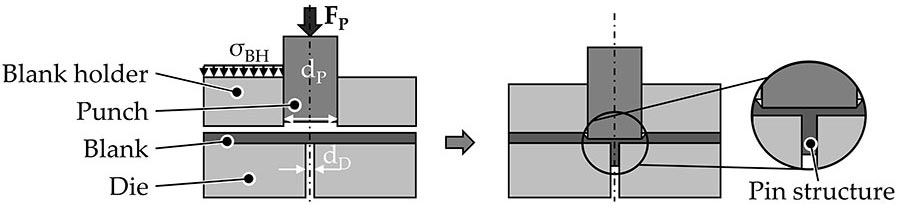
This illustration shows the process of extruding pin structures from sheet metal. Source: Institute of Manufacturing Technology

For their study, the researchers varied the length of the pins, the number of pins, and the arrangement of the pins. Source: Institute of Manufacturing Technology
A major challenge with this method is how to form the pins in one of the parts. Several processes are available. Additive manufacturing processes include cold metal transfer, arc percussive micro-welding, and various powder-based processes, such laser metal deposition. Subtractive processes include classical machining, micro-machining, and the Surfi-Sculpt process. Metal injection molding can also be used.
All of these techniques have their advantages. With additive manufacturing, for example, there are virtually no limitations to the geometric design of the pins. As a result, the geometry can be adapted specifically to the application.
On the other hand, all these methods are time-consuming and difficult to integrate into existing manufacturing processes. For pin joining to gain widespread adoption, cycle times must be short, the process must integrate easily with existing production lines, and it must adapt quickly to changes.
Cold forming meets those requirements. Single- and multi-pin structures can be produced quickly in one stroke. In addition, the process offers the advantage of strain hardening, which has a positive effect on the strength of the pins and thus on joint strength. The process also provides an excellent surface quality, which can have a positive effect on fiber rearrangement when pressed into FRP.
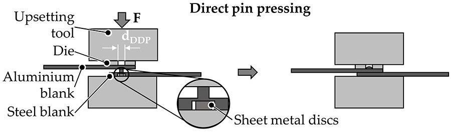
To create an assembly, the softer aluminum sheet is pressed into pins on the harder steel sheet. Source: Institute of Manufacturing Technology
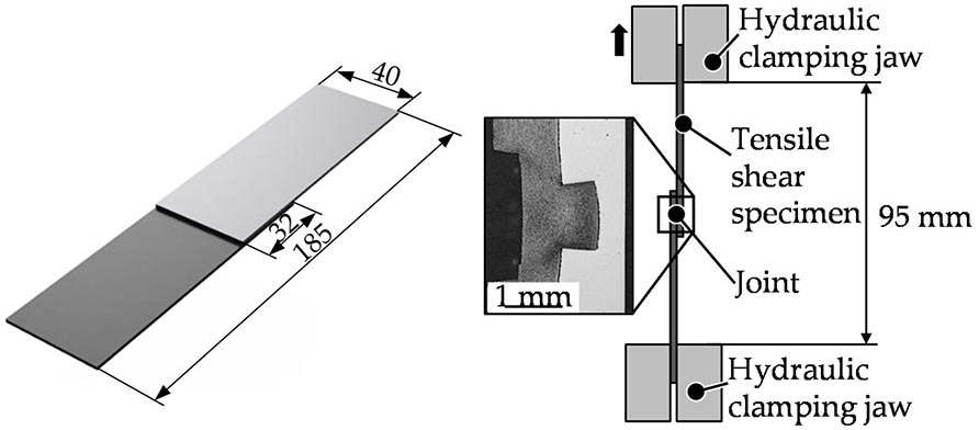
This diagram shows the arrangement used to measure the shear strength of the assemblies. Source: Institute of Manufacturing Technology
Our Study
We set out to demonstrate the feasibility of using cold-formed pins to join DP600 steel and EN AW-6014 aluminum alloy. In the automotive industry, DP600 steel is frequently used for body parts, structural components and crash-relevant components, such as cross-members. The steel is cold-rolled and galvanized. The EN AW-6014 aluminum is also cold rolled. It’s typically used for hoods, doors and fenders, as well as structural applications.
For our study, we used specimens 108.5 millimeters long, 40 millimeters wide, and 1.5 millimeters thick. Pin height varied from 1.08 to 1.86 millimeters.
The pins were produced in the DP600 steel sheet by cold extrusion. A multi-acting tool, in which the blank holder and the punch can move independently of each other, was used. To prevent the steel sheet from bulging and reduce material flow radially outwards, a constant blank holder pressure of 250 megapascals was applied.
The pin structure is formed by moving the punch, 3 millimeters in diameter, axially at a constant speed of 5 millimeters per minute. The material is displaced both axially into a die with a diameter of 1.5 millimeters and laterally outwards into the sheet plane and the cavity. The pin height can thus be adjusted by the axial punch penetration depth, where a higher pin is realized by greater penetration of the punch into the sheet metal. To regulate the penetration depth of the punch, height-adjustable mechanical stops are used.
For our study, we varied the length of the pins, the number of pins, and the arrangement of the pins.
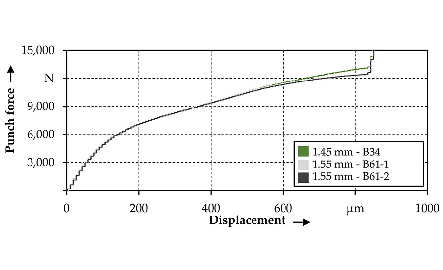
The force-displacement curves for multi-pin assemblies was similar to that of single-pin assemblies. Source: Institute of Manufacturing Technology
For assembly, the steel sheet was pressed directly into an unperforated aluminum sheet using a Walter + Bai 300 universal testing machine and a conventional upsetting tool. The tool moves axially at a constant speed of 5 millimeters per minute and presses the pin structure into the aluminum sheet until a force threshold of 25 kilonewtons is reached.
In the case of direct pressing of single pins, two strategies were examined: with and without a round die. The diameter of the die was varied between 3 and 4 millimeters. The aim was to investigate whether the material flow and thus the formation of an undercut can be promoted with the die.
To prevent the sheet metal from fracturing or bending back into the punch cavity underneath the pin structure, fine sheet metal discs were placed in the punch impression to provide axial support for the pins during joining. (When pressing multi-pin structures, no dies were used.)
The shear strength of all the assemblies was then measured.

These graphs show of the surface profiles of a single and multi-pin structure, as well as the sheet thickness across the width of the sample: (a) surface profiles of the measured specimens, (b) corresponding sheet thickness, (c) detailed view of the red area marked in subfigure (b) and (d) detailed view of the blue area marked in subfigure (b). Source: Institute of Manufacturing Technology
Direct Pin Pressing
The pressing process can be divided into three phases.
Phase 1 begins with a linear increase in force while the system deforms elastically, both with and without a die. As the joining process progresses, the force increases further due to work hardening and plastic deformation. Shortly after a tool displacement of approximately 0.3 millimeter and a force of 1,100 newtons, a plateau with a constant tool force is reached. Here, the stress in the aluminum sheet introduced by the pin is so high that the material is axially displaced by the pin into the die, with the pin acting as a kind of shear punch. As the penetration of the pin progresses, a slight decrease in force can be detected due to the decreasing residual sheet thickness above the pin.
Phase 2 then begins with the abrupt failure of the aluminum sheet, at a displacement of about 1.1 millimeters. The force drops rapidly to 270 newtons, then further to almost zero, and subsequently stays there until the tool displacement has reached the pin height. The drop in force is due to the formation of a circular crack on the surface of the aluminum sheet. The crack continues to propagate until the material has been separated completely and a circular hole has formed.
Phase 3 begins when the aluminum comes into contact with the surface of the steel. The force increases linearly due to the elastic deformation and marks the end of the joining process.
The force-displacement curve for the multi-pin assemblies was similar. However, the force requirement increases linearly with the number of pin structures. For example, with 1.45-millimeter pins, phase 2 starts at a displacement of 1.38 millimeters and force of 6,336 N for the multi-pin specimen, compared to a displacement of 1.3 millimeters and a force of 3,200 newtons for a single-pin assembly.
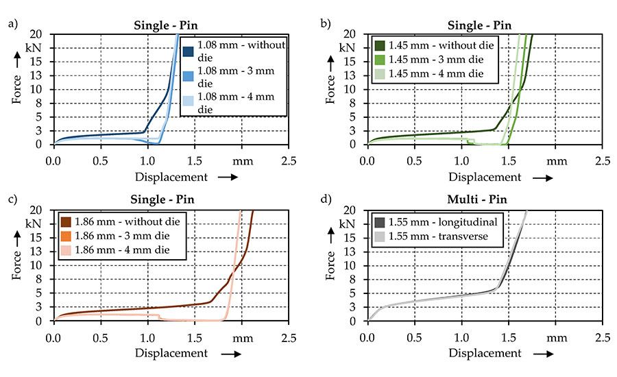
Here are the force-displacement curves (a) when joining 1.08 millimeter pins with and without a die, (b) 1.45 millimeter pins with and without a die, (c) 1.86 millimeter pins with and without a die and (d) 1.55 millimeter multi pin structures. Source: Institute of Manufacturing Technology
Tensile Shear Testing
Our data indicate that tensile shear strength increases with the height of the pins. For a pin height of 1.08 millimeters, a maximum tensile shear force of 766 ±13 newtons was achieved. For a pin height of 1.45 millimeters, the maximum tensile shear force was 938 ±35 newtons, which is 22.5 percent higher than that for the 1.08-millimeter pins. By increasing pin height to 1.86 millimeters, the tensile shear strength increased to 1,025 ±30 newtons, which is 33.7 percent higher than that for the 1.08-millimeter pins.
This increase in tensile shear strength can be attributed to the improved form fit. When longer pins are inserted into the joining partner, more pin volume is compressed, which increases the maximum head diameter of the pin and thus increases the form fit. With a pin height of 1.08 millimeters, the maximum head diameter is 1.64 millimeters. With a pin height of 1.45 millimeters, the head diameter is 1.68 millimeters. And, with a pin height of 1.86 millimeters, the head diameter is 1.71 millimeters.
The increased form fit with taller pins is also evident when looking at the damage patterns from tensile testing.

This image shows micrographs of the various joints produced in this study: (a) 1.08 millimeter pin joined without a die, (b) 1.08 millimeter pin joined with 3 millimeter with a die, (c) 1.08 millimeter pin joined with a 4 millimeter die, (d) 1.45 millimeter pin joined without a die, (e) 1.45 millimeter pin joined with a 3 millimeter die, (f) 1.45 millimeter pin joined with a 4 millimeter die, (g) 1.86 millimeter pin joined without a die, (h) 1.86 millimeter pin joined with a 3 millimeter die, (i) 1.86 millimeter pin joined with a 4 millimeter die, (j) two 1.55 millimeter pins in a longitudinal arrangement, and (k) two 1.55 millimeter pins in a transverse arrangement. Source: Institute of Manufacturing Technology
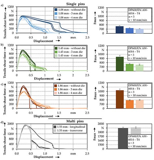
These are the tensile shear force-displacement curves, corresponding maximum force, for the various assemblies: (a) 1.08 millimeter single pins joined with and without a die, (b) 1.45 millimeter single pins joined with and without a die, (c) 1.86 millimeter single pins joined with and without a die, and (d) two 1.55 millimeter pins. Source: Institute of Manufacturing Technology
With a pin height of 1.08 millimeters, the pin is almost undamaged after shearing. This is because the bending moment at the connection point between the pin and the sheet metal is significantly smaller than with larger pins. Since the steel is much stronger than the aluminum, the latter is plastically deformed. After reaching the maximum tensile shear strength, the form fit is reduced due to the plastic deformation and the aluminum is grooved. With increasing shear pull, the form fit decreases until the pin is completely pulled out of the aluminum.
With a pin height of 1.45 millimeters, the aluminum is also deformed plastically at the beginning of the tensile shear test. After reaching the tensile shear strength, the force decreases continuously. This is explained by the fact that the pin structure in the joining partner is slowly sheared off as a result of the good form fit. At the same time, the cross section at the pin structure’s junction with the sheet metal continues to decrease. After a certain displacement value, the pin is sheared off due to the reduced cross section and the associated higher stress.
The tensile shear strength of the pins pressed without a die was higher than that of the samples pressed with a die, independent of pin height. However, the samples pressed with a die were very similar in terms of shear strengths. Thus, the die diameter had only a minor effect on the tensile shear strength.
Looking at the multi-pin assemblies, the tensile shear strength increased significantly by adding another pin. For example, at a pin length of 1.45 millimeters, two pins in a longitudinal arrangement produced a tensile shear strength of 1,898 ±22 newtons, a 102 percent increase compared with a single pin. Similarly, two pins in a transverse arrangement produced a tensile shear strength of 1,915 ±12 newtons, a 104 percent increase.
Similar results were obtained for other pin heights: Adding an extra pin leads to a doubling of the maximum tensile shear strength.
Conclusions and Outlook
Based on the experimental results obtained in this work, the following conclusions can be drawn:
- Cold extrusion is suitable for producing pin structures in DP600 steel.
- Pin structures are suitable for joining dissimilar metals.
- For the production of load-bearing joints, the control of the material flow during joining is essential, as a good form fit during direct pin pressing is decisive for good tensile shear strength. The form fit should withstand enough load to prevent the pin structure from being pulled out of the joining partner prematurely and that the pin itself fails instead.
- The use of a die when joining with metallic pin structures has the potential to influence the material flow and thus the formation of the form fit. However, consideration must be given to the differences in strength of the joining partners to avoid the pin structure piercing the joining partner, which would lead to inferior joint quality.
- The pin structure height has a significant influence on joint strength. With increasing pin height, the joint strength can also be increased.
- By increasing the number of pins, the connection strength is increased linearly.
The future research could investigate multi-pin structures with larger pin arrays. Additional research could also look at how the process works with materials of different strength gradients—specifically, on how that affects the formation of an undercut.
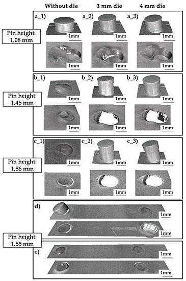
This shows the damage patterns of the joints after tensile shear strength testing. The steel sheet is on top; the aluminum sheet is on the bottom: (a1) 1.08 millimeter pin joined without a die, (a2) 1.08 millimeter pin joined with a 3 millimeter die, (a3) 1.08 millimeter pin joined with a 4 millimeter die, (b1) 1.45 millimeter pin joined without a die, (b2) 1.45 millimeter pin joined with a 3 millimeter die, (b3) 1.45 millimeter pin joined with a 4 millimeter die, (c1) 1.86 millimeter pin joined without a die, (c2) 1.86 millimeter pin joined with a 3 millimeter die, (c3) 1.86 millimeter pin joined with a 4 millimeter die, (d) 1 two 1.55 millimeter pins in a longitudinal arrangement, and (e) two 1.55 millimeter pins in a transverse arrangement. Source: Institute of Manufacturing Technology
Editor’s note: This article is a summary of a research paper co-authored by Martin Kraus and Marion Merklein of the Institute of Manufacturing Technology. To read the entire paper, click here.
ASSEMBLY ONLINE
For more information on sheet metal assembly, read these articles:
Techniques for Joining Sheet Metal
Tacks for Sheet Metal Assembly
Assembly Presses: Pins and Dowels
Looking for a reprint of this article?
From high-res PDFs to custom plaques, order your copy today!


