Challenges in Automatic Screwdriving

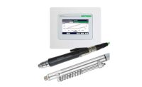
A vacuum hose attached to this screwdriving spindle keeps the fastener on the bit when reaching into recesses. Photo courtesy DEPRAG Inc.

DEPRAG’s sword feeder is an alternative to vibratory bowls for feeding screws. The feeder handles screws more gently than a bowl and operates more cleanly. Photo courtesy DEPRAG Inc.

This automatic screwfeeding system can be programmed not to feed another screw unless the previous fastener has been installed correctly. Photo courtesy ASG Div. of Jergens Inc.

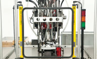
This four-spindle automatic screwdriving machine secures the cover for a gasketed electronics assembly. Photo courtesy Design Tool Inc.

This automatic screwdriver is equipped with unique tooling that allows it to install screws in confined spaces. The jaws mechanically hold onto the screw until it is started in the target hole. Once the screw is started, the jaws swing out toward the one open side. Photo courtesy Dixon Automatic Tool Inc.

This screwdriving system is equipped with two rotary bowl screwfeeders. Each bowl holds 12 pounds of screws and delivers more than 30 screws per minute.

A logic control module alternates feeders each time a “cycle completed” signal is received from the driver. A screw is then blow-fed to a multiport manifold that directs screws from either feeder to a single port. Photo courtesy Nasco Industries Inc.


From a distance, the antennas atop a cell-phone tower don’t look that big. In fact, those “little” white boxes are 4 to 12 feet long, 2 feet wide and 1 foot deep. These boxes may be packed with sophisticated electronics—but it’s all held in place with screws. A typical antenna might contain hundreds of screws in more than a dozen different sizes and types.
Such was the challenge presented recently to the ASG Division of Jergens Inc. The application posed several problems. The first was to design equipment that could access every location in the assembly. Another was to ensure that the large, expensive and somewhat fragile electronic subassemblies were not damaged during installation of the screws. A final challenge was error-proofing. With so many screws to install, the antenna manufacturer needed a way to ensure that every screw was installed.
In this case, the challenge was less about screwfeeding and more about process control. DC electric screwdrivers solved the problem. “In the early days, when all you had were air tools, that would have been a very difficult application,” says Phil Klingler, product manager for ASG. “There was no intelligence in the tool.”
These days, electric tools give engineers control over torque, angle and driver speed. The controller can be programmed not to feed another screw unless the previous fastener has been installed correctly. Similarly, an electronic counter can keep track of the number of fasteners that have been installed. The controller can be programmed to not release an assembly unless the right number of screws have been driven.
From cell-phone antennas to car parts to medical devices, suppliers of automatic screwdriving systems see a lot of applications on a daily basis. Some are easy to automate, while others…not so much. Deep counterbores, short fasteners, little or no clearance around fastening locations—such issues make a screwdriving application challenging to automate, but not impossible. Automation engineers have found many ingenious ways to solve screwdriving problems.
Make Room
The most common challenge for automatic screwdriving is space. Autofeed screwdrivers need enough room around each fastening location to accommodate the tooling that accepts the screws. Fastening locations in deep recesses or abutting vertical walls are less than optimal.
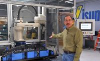
“In an ideal world, we’d like at least 0.5 inch of clearance around the location where the head of the screw is installed,” says Jarrod Neff, marketing manager for Visumatic Industrial Products. “We also need quite a bit of space above the assembly for the tooling and the driver.”
If obstructions can’t be designed out of the assembly, engineers still have options. Special tooling can be designed to go down into a recess and mate with the part. Alternatively, the driver can be equipped with a vacuum to keep the fastener on the bit until it reaches the hole.
Sometimes, changing the fastener can help, too. Neff recalls working on a medical device application that called for screws to be installed in recesses 5 inches deep. “The manufacturer was using a screw with a sharp point,” he says. “If the screw wasn’t perfectly aligned, it would bore into the side of the recess instead of the hole. Switching to a fastener with a blunt point took care of the problem.”
The Right Fastener
As that medical device application illustrates, the fastener itself can be common source of problems with automatic screwdriving. The best screws for automation are those with internal drive recesses, such as Torx and Torx Plus. These drive styles require less downward force to keep the bit engaged. The bits also line up better and stay within the centerline of the fastener.
Kevin Buckner, director of engineering at Design Tool Inc., recommends using quality fasteners to avoid problems with feeding and driving. The screws should also have a length-to-diameter ratio greater than 1-to-1 in order to be blown to the driver location. Screws that are wider than they are long will tumble in the feed tube.
If short, wide fasteners can’t be avoided, there are options. One possibility is to blow the screws through extruded tubing with the same profile as the fastener. A more common approach is to feed the screws on a linear track to a pick point. In this case, a robot or an operator must go to the pick point to a retrieve a screw after each insertion. And that, of course, will increase cycle time.
To mitigate that problem, at least with robotic screwdriving, DEPRAG Inc. has come up with a unique solution: small magazines attached to the driver. Now, instead of retrieving only one screw at a time from the pick point, the robot can get three or four, explains Boris Baeumler, applications engineer at DEPRAG. If the assembly only needs three or four screws, the robot can be picking up fasteners while an operator unloads and reloads the fixture.
For larger, higher-volume applications—such as installing flow drilling screws with a six-axis robot—DEPRAG has developed a revolving 30-screw magazine.
Cleanliness Is Next To…
High-volume screwdriving can be a dirty business. Bouncing hundreds of screws around in a vibratory bowl day and night can generate a lot of particulates. So, too, can the driving process itself. On most assembly lines, particulate generation is not an issue. But for other products, such as medical devices or automotive sensors, particulate generation is a big deal.
Here, too, equipment suppliers have risen to the challenge. One option for cleanly feeding fasteners is DEPRAG’s sword feeder. Protruding from the bottom of a wedge-shaped rectangular hopper is a blade with a slot cut into it. As the blade rises on an angle through the hopper, fasteners fall into the slot, shank first, and slide down to the escapement. Because of its gentle action, the sword feeder generates less particulate than vibratory bowls and drum feeders.
For additional cleanliness, vacuum lines can be attached to the hopper, the feed track, and even the nosepiece of the driver to suck up particulates.
Keep a Lid on It
Design Tool recently built a screwdriving system for a challenging electronics application. The application involved assembling a cover to an electronics assembly with seven screws. The cover was sealed with an O-ring, and the assembly had to pass a leak test after the cover was installed, making the seal critical. A clamping mechanism was required to maintain O-ring compression until all the fasteners were installed. The fastener was an M3.5 x 10 millimeter pan-head TORX Plus thread-cutting screw. Total assembly time needed to be less than 22 seconds to keep pace with the assembly line.
“The most challenging aspect of the application was packaging all the components in such a manner that the machine could meet the production rate, while still allowing access to all the components for serviceablility,” says Buckner. “The design envelope was less than 5 inches by 5 inches, making packaging the clamp mechanism and screwdriving components difficult.”
Design Tool solved the packaging problem by building a four-spindle automatic screwdriving machine that incorporated a pneumatic swing clamp and four individual platen assemblies for driving the screws. The platen assemblies were mounted on linear bearings to enable them to shift positions to accommodate the bolt pattern. A complete controls package with a PLC, valves and plumbing components was built to operate the machine.
The machine was equipped with a four-exit feed system that supplies four, then three, screws sequentially. The feeder bowl was equipped with a 1 cubic foot supply hopper that could hold 20,000 screws, which extended the time between refills.
The machine was also equipped with full guarding and a light curtain to prevent operator intrusion into the work envelope once the machine cycle was started. A tower light indicates a completed assembly with a green light. A red light indicates an emergency stop condition.
In operation, the machine clamps the cover to the assembly body and lowers and drives the first four screws. After driving the screws, the machine elevates the platen assemblies to clear the clamp mechanism, then shifts the platen positions and lowers and drives the remaining three screws. Once the cycle is completed, the platen assemblies elevate and return to the start position, and the swing clamp releases the assembly.
The actual run time of the machine is less than 13 seconds, allowing 9 seconds for loading and unloading while maintaining the required 22-second cycle time.
Driving in a Tight Spot
Dixon Automatic Tool Inc. was asked to provide automatic equipment to install four trilobular thread-forming screws in an electrical terminal assembly. The #10 screws were 5/16 inch long with a binding head and a combination slotted and Phillips recess. Similar to pan heads, binding heads have a deeper slot and are slightly undercut beneath the head. They are often used for electrical work.
All four driving positions had confinements or walls on three of the four sides. The wall height was taller than the length of the screw shank, and the distance between the walls was 0.395 inch. The screw head measured 0.39 inch in diameter.
“This creates a condition where the screw cannot be presented to the target hole and controlled using conventional jaw tooling or vacuum tooling,” explains Brian Droy, Dixon’s vice president of sales. “Screwdriving applications with these conditions are often performed by an operator that will hand position and drive the screw.”
To solve the problem, Dixon developed unique jaw tooling for its Model SD-111 automatic screwdriver that can install screws in confined spaces. The jaws mechanically hold the screw until it is started in the hole. Once the screw is started, the jaws swing out toward the one open side. This dramatically improves the success rate of the screwdriving process.
60 Screws per Minute
On a recent project handled by Nasco Industries Inc., the problem wasn’t so much the fastener or the assembly design, but rather the volume. Nasco was tasked with feeding a 2-inch long, ¼-20 trilobular screw. The customer wanted the feeder to hold more than 20 pounds of screws without using a separate feeder bowl for storage. The system would have to supply fasteners at a rate of 60 screws per minute.
To solve the problem, Nasco designed a system with two rotary bowl screwfeeders, says Ed Brenner, marketing manager at Nasco. Each bowl holds 12 pounds of screws and can deliver more than 30 screws per minute. A floating stabilizer in the feeder prevents minor variations in screw head size from jamming the system.
A logic control module alternates feeders each time a “cycle completed” signal is received from a screwdriver, inserter or PLC. A screw is then blow-fed to a multiport manifold that directs screws from either feeder to a single port.
“The result is a feed rate of more than 60 screws per minute, a screw capacity of 24 pounds, and a workstation footprint smaller and less expensive than a large, multitrack vibratory bowl,” he says.
Looking for a reprint of this article?
From high-res PDFs to custom plaques, order your copy today!


