High-strength aluminum is a key material for reducing weight in auto body applications. However, the material’s low ductility at room temperature can cause cracking issues with conventional mechanical fastening methods.
A new process—friction self-pierce riveting—promises to solve that problem. The process combines the mechanical joining mechanism of self-pierce riveting with the solid-state joining mechanism of friction-stir spot welding.
Under heat effects from friction and plastic work, the strength and ductility of the joined materials, as well as the force required for joining, are very different from that of self-pierce riveting (SPR). Mechanical performance and fatigue life of the joint are also improved, because of the increased local hardness of the aluminum due to grain refinement and the formation of solid-state joining.
To achieve a high-strength joint with this technique, the rivet, die and process parameters must be optimized to match the materials. For instance, to facilitate mechanical interlocking, the rivet should have an appropriate tip angle and adequate strength relative to the base materials. Similarly, the flaring of the rivet is influenced by the depth of the die cavity and the depth of rivet penetration. On the other hand, the plunging speed and depth, as well as the rotation speed of the rivet, will influence how much frictional heat is generated to soften the materials.

Illustration A shows an aluminum-intensive body-in-white design. Illustration B shows examples of the complex shapes involved of body-in-white structures, along with the location of joints assembled with friction stir welding. Illustration C shows clamping strategies for a flat bead on metal sheets using friction stir welding. Illustration D shows a new approach using spot joints produced by friction SPR. This promises to reduce complex clamping design and excessive clamping force prior to friction stir welding. Source: Soochow University
Often, engineers rely on trial and error to determine these parameters. However, there is a better alternative. Numerical modeling is a cost-effective way to predict joint formation under given process conditions and performance requirements.
Although numerical models have been created for friction stir welding, simulation of friction SPR has been less developed. That’s because it’s a more complex process.
Compared with conventional SPR, friction SPR is not strictly axisymmetric, given the high-speed rotation of the rivet. In addition, heat generation and thermal conduction must be simulated to account for frictional heat effects on material softening. Compared with friction stir welding, the rotating element in friction SPR is much smaller.
We set out to develop a thermomechanical model to predict temperature distribution and rivet flaring during friction SPR. We then used that model to develop an ideal fastener for joining high-strength, low-ductility aluminum alloy 7055 using friction SPR. We investigated the influence of rivet tip angle, material strength, and die cavity design on interlocking distance and joint failure load.
To streamline our iterations of rivet design, a static numerical model was employed to refine rivet head height and shank diameter. Based on guidance from the model, we designed a rivet and die for the friction SPR process. Real-world joint formation and performance were then compared with numerical models.
Our goal was to advance the friction SPR technique for joining multiple sheets and dissimilar material combinations typical of body-in-white assemblies. We also hoped to reduce the amount of clamping needed for the joining process.
Clamping is critical for friction stir welding. High force and complex fixtures are needed to securely hold the parts in place. This can be a challenge when assembling automotive parts with complex shapes and contours. Friction SPR addresses this issue by functioning as a spot-joining technique, effectively securing the body parts before a linear weld is accomplished. An added benefit of friction SPR lies in its ability to contribute supplementary mechanical joint strength alongside a linear weld.
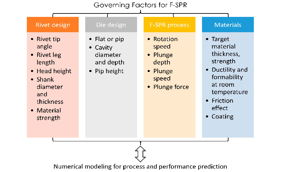
Many factors affect the strength of joints produced by friction SPR. Source: Soochow University

We created a finite-element model of the friction SPR process with the coupled Eulerian and Lagrangian method. Illustration A shows the mesh division and Eulerian domain. Illustration B predicted temperature distribution after a plunge depth of 1.5 millimeters. Source: Soochow University
Modeling Approach
The key factors in forming a sound friction SPR joint include the geometric design of both the rivet and die, the rivet material, sheet material, and the process parameters, such rotation speed, plunge speed, and plunge depth. Rivet geometry is particularly important. The plunging depth should be equal to or slightly exceed the leg length of the rivet to form a tight contact and interlocking distance. Meanwhile, the plunging depth should not be so large that it prevents the penetration of the rivet through the bottom sheet and reduces the amount of chips on the top sheet surface.
The rivet head must be designed to sustain the torque and axial force of the joining process. It must also have a minimum height for load-bearing capacity. Since the rivet head will be exposed to corrosive environments during vehicle operation, its surface area should be minimized. For the die’s geometry, the cavity depth and diameter define the volume of the extruded material of both the rivet leg and the target sheet. Thus, the leg length of the rivet should fit the thickness of the stacked sheets and the cavity depth.
On the material property side, the strength of the rivet and sheet will depend on the temperature and microstructure, which are directly related to heat generation and the strain rate during the riveting process. The higher the rotation speed and plunge speed are, the greater the heat generation and strain rate will be. In addition, the maximum strain caused by the joining process will assist the rivet in piercing the sheet material, as well as challenge the ductility of the sheet on the bottom side. Therefore, the die cavity must be designed to enable rivet flaring, and the plunge depth should be precisely controlled to avoid fracturing the bottom sheet.
To achieve these goals, a large number of experiment trials must be conducted, which is neither efficient nor effective in revealing the critical parameters of the joining process. Instead, we used numerical modeling is to perform this work.
We created our numerical model of friction SPR using Abaqus finite element analysis software from Dassault Systemes. The coupled Eulerian-Lagrangian approach was employed to simulate the transient temperature, plastic flow and rivet penetration during friction SPR.

We set out to design an ideal rivet for joining high-strength aluminum sheets. The left illustration shows the original design. The right illustration shows the refined design. Source: Soochow University

This image shows our experimental setup and the initial design of the rivet and die. Source: Soochow University
The thickness of the aluminum sheets is 2.5 millimeters, and a flat die with a cavity depth of 1.5 millimeters was employed. The rivet, holder and die are modeled with Lagrangian elements, which describe the deformation behavior of the material captured by the initial configuration. On the other hand, the aluminum alloy sheets were modeled with Eulerian elements, through which the material can flow in and out of the fixed mesh.
The ductile fracture model was used to predict the onset of damage by assuming that the equivalent plastic strain at the onset of damage is a function of stress triaxiality and strain rate. The fracture strain is assumed to be the elongation of material at a specific temperature, and the strain rate effect is ignored.
After damage initiation, the material stiffness starts to degrade gradually before reaching the maximum effective strain. The element stiffness is reduced to a very small fraction of the original value to enable material separation. The temperature-dependent material properties of the aluminum sheet and steel rivet are based on data from the literature.
The yield strength refers to the strength at 0.2 percent of strain, and the hardening behavior was modeled as linear hardening. The friction coefficient is 0.4 throughout the analysis. Given the small mesh size used to fit the curvature of the rivet tip, the number of elements in the model is greatly increased, and the time step is reduced to nearly 1 nanosecond. As a result, a large amount of computational power is required, and the analysis event is limited to subseconds.
During the initial stage of friction SPR, a peak temperature around 500 C appears in the rivet tip because of high contact stress and frictional heat generation. The overall temperature of the aluminum sheet ranges from 200 to 300 C, which is significantly below the melting point of the metal, but still high enough to enhance ductility. The temperature difference between the rivet and sheet comes from the high thermal conductivity of the aluminum relative to that of the steel rivet.
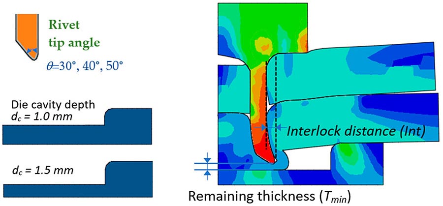
The geometries of the rivet and die have a decisive effect on both joint formation and performance. Source: Soochow University
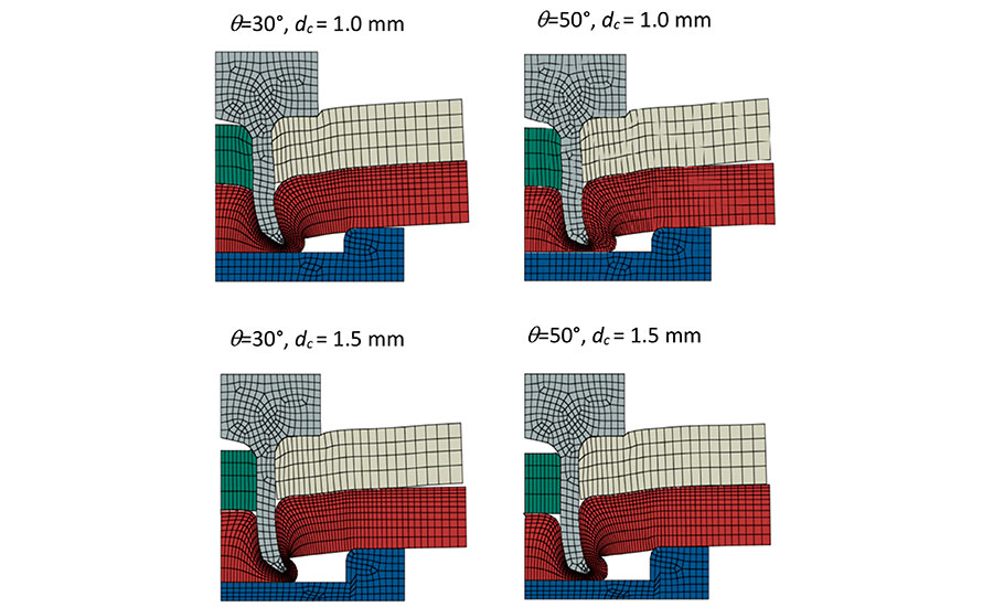
This illustration shows the influence of rivet tip angle and die cavity on rivet-flaring performance. Source: Soochow University
To create an accurate process simulation, it is necessary to derive an approximate model by capturing the essential features, such as heat, friction force, and pressure distribution. A simplified 2D model with equivalent temperature distribution and shear force was proposed to serve this purpose. The axisymmetric model was employed, considering the geometric features of the rivet and the die cavity.
Temperature distribution obtained from the 3D model was introduced to the 2D model as a thermal boundary condition. In this study, the temperature of the model at a rivet-plunge depth of 1.2 millimeters was used as the source of data mapping. During the friction SPR process, this temperature field is kept constant on the nodes of Lagrangian elements, but it changes with the deformation of the rivet and the aluminum sheets. The heating becomes relatively stable as the rivet penetrates the aluminum to a certain depth. The frictional shear force is along the circumferential direction in the actual process, but the application of such forces is limited in the axisymmetric element.
Instead, a friction force in the radial direction was applied to mimic the loading condition necessary for material yielding. In addition, given the significant material softening caused by heat generation, the penetration of the top sheet was assumed to have a negligible impact on the mechanical behavior of riveting at the bottom sheet. Thus, the top sheet was prepared in a configuration of full rivet penetration to avoid numerical instabilities due to the extreme squeezing and subsequent deleting of elements in the model.
To evaluate the geometrical factor of joint strength, a performance model is also necessary to refine the design parameters and minimize the design variability as much as possible. In this study, the standard lap-shear test configuration and the cross-tension test for riveted joints were numerically investigated.

This illustration shows the impact of interlocking distance at different die cavity depths and rivet tip angles. Source: Soochow University

This illustration shows performance modeling of a riveted joint with a shank diameter of 5.2 millimeters. Source: Soochow University
Experiment Setup
For our study, we modified a benchtop friction stir welding machine to perform friction SPR.
Coupons of aluminum alloy 7055 were assembled in a lap-shear joint configuration using a hollow steel rivet with a shank diameter of 6.8 millimeters and a wall thickness of 0.94 millimeter. The rivet head was hexagonal with a height of 2.54 millimeters to ensure tight contact between the rivet and the driver. A magnetic pin was installed inside the driver to hold the steel rivet before joining. The outer fillet of the rivet head was 0.5 millimeter, and that of the rivet tip was 0.2 millimeter. The length of the rivet was 6 millimeters to cover the total thickness of the two sheets (2.5 millimeters for each sheet) and the major part of the die cavity depth (1.5 millimeters). The rivet material was 1018 carbon steel with a yield strength of about 455 megapascals (MPa) at room temperature.
The inner diameter of the die cavity was 8.2 millimeters, and the outer diameter was 10.8 millimeters. The pre-tightening load of the die was determined by a fixed torque in a calibrated wrench. Small round bars inserted into several pre-drilled holes around the test pieces were used to limit the rotational movement of the sheets during friction SPR. After the preliminary experiment, the plunge speed was set to 2.86 millimeters per second, and the plunge depth was 6.045 millimeter. The rotating speed of the driver tool was 3,000 rpm.

This illustration shows performance modeling of riveted joint with a shank diameter of 7.8 millimeters. Source: Soochow University
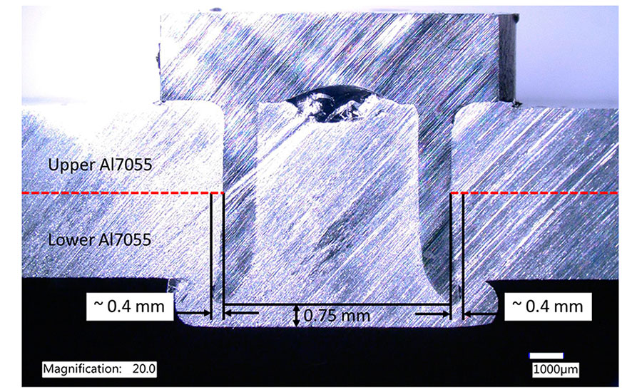
This cross-section shows the rivet shape and interlocking performance after the first iteration of our design. Source: Soochow University
Rivet Tip Angle and Die Cavity Depth
The geometry of the rivet and die has a decisive effect on both joint formation and performance. More specifically, the rivet tip angle, as well as the die cavity depth, should be designed to match the sheet stack-up and material properties.
Mechanical interlocking is a function of the remaining thickness of any given rivet or tool geometry. The reason for using the remaining thickness as an indicator is that plunging depth can be a variable of sheet thickness and rivet length. Three tip angles—30, 40 and 50 degrees—were studied numerically. In addition, two cavity depths, 1 millimeter and 1.5 millimeter, were examined under two thickness cases, 0.35 millimeter and 0.5 millimeter.
We found that, under the same remaining thickness, a rivet with a 30-degree tip angle provides greater mechanical interlocking than a rivet with a 50-degree tip angle. By reducing the remaining thickness from 0.5 millimeter to 0.35 millimeter, the interlocking distance can be further increased by 60 percent. By using a shallower die (cavity depth of 1 millimeter), the interlocking performance becomes slightly better at the cost of greater plunging force. Under the same remaining thickness, a shallower die cavity tends to make the rivet leg thicker because of significant hydrostatic pressure.
A smaller remaining thickness, 0.35 millimeter, resulted in a doubled interlocking distance compared with a remaining thickness of 0.5 millimeter, which indicates that the rivet length and plunging depth can be refined to achieve the best performance of the rivet. On the other hand, a sharper rivet angle leads to increased mechanical interlocking with a shallower die. It can also be concluded that the rivet-interlocking behavior is less sensitive to rivet tip angle with a die cavity depth of 1.5 millimeters.
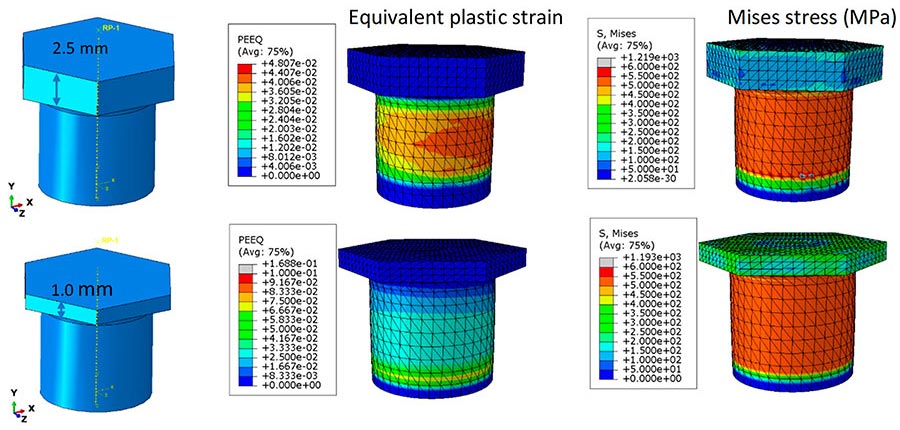
This illustration shows a static analysis of the rivet under an axial compression load of 10 kN and a torque of 5 newton-meters. Source: Soochow University

This illustration shows cross-tension performance modeling for 1-millimeter rivet head. When no solid-state joining is considered, rivet pull-out failure is predicted from cross-tension testing. Bottom aluminum fracture is predicted when solid-state joining between the rivet and surrounding aluminum materials is considered. Source: Soochow University
Effect of Rivet Shank Diameter and Material Strength
Load-carrying capacity depends on the interlocking distance as well as the rivet cross-sectional area, which is a function of the rivet shank diameter and wall thickness. In addition, the rivet material strength plays a critical role in governing the joint strength.
For a given interlocking distance, a performance model can be employed to conduct a sensitivity study on the rivet shank diameter, as well as its material strength. Two rivet diameters were numerically studied: 5.2 and 7.8 millimeters. Wall thickness was kept the same for both. The tensile strengths of the rivets were 560 and 780 MPa. Only half the model was considered, given the symmetry in evaluating the joint shear strength.
When the rivet shank diameter is 5.2 millimeters, the peak load is below 6 kilonewtons (kN) because a small effective joint area sustains the shear load. The rivet fractures at the cross-section near the joint interface between the aluminum sheets.
When the rivet shank diameter is increased to 7.8 millimeters, the peak load is above 10 kN. The joint exhibited a button-pull-out failure mode rather than a rivet failure. It is interesting to note that the joint without an interlocking distance also delivered a shear load just 2 kN less than the joint with an interlocking distance of 0.6 millimeter. This is because the shear load direction is normal to the rivet axial direction, and the effective load-bearing area is more than 45 square millimeters.
Based on this analysis, the rivet was designed with a larger diameter of 7.2 millimeter, a tip angle of 30, and a die cavity depth of 1.2 millimeter.

This optical macrograph shows cross-sections of aluminum sheets riveted with the friction SPR process. Images B and C show solid-state joining between the upper and lower sheets. Source: Soochow University

This magnified optical image (a) of the joint interface on the left side shows solid-state joining between the upper and lower aluminum sheets and a grain refinement area marked in zone II. The magnified optical image (b) of the rivet tip region on the left side of the joint shows refined grain. Source: Soochow University
The overall rivet flaring and aluminum sheet bottom finishing are satisfactory, although there is a slight lack of material fill inside the rivet, which indicates the plunging depth can be further increased. This is also evidenced by the large remaining thickness, which is about 0.75 millimeter. On the other hand, the rivet head seems to have redundant material, which will increase the weight of the friction SPR joint. The rivet has a sharp tip for penetrating material, and thus, mechanical interlocking is greatly increased, which is promising for achieving higher lap-shear strength and cross-tension capacity loads.
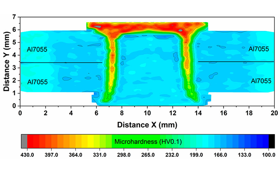
This images shows Vickers microhardness mapping of the refined riveted joint. Source: Soochow University

The researchers conducted lap-shear tensile tests and cross-tension tests on four samples. Our joints achieved an average peak failure load of 11.3 ± 0.35 kN. The failure mode of all four coupons was the bottom sheet pulling out at the joint, indicating good mechanical interlocking and solid-state joining between the aluminum sheets and between the aluminum and the rivet. Source: Soochow University
Rivet Head Height Reduction
Based on these results, we further optimized the design of the rivet.
The rivet head represents another geometric factor that can influence the mass added to the joint and the load transferred from the driver to the rivet leg. The original design of the rivet features a height of 2.54 millimeters to ensure torque delivery and driver-rivet alignment. In the new rivet design, the internal cavity shape in the rivet head is first removed because of the remaining cavity after joining. Then, a static load analysis of the rivet is performed to evaluate the plastic strain produced under the combined load.
In the numerical model, the displacement at the bottom region of the rivet leg is fixed in all three directions. An axial force of 10 kN is applied to the top surface of the rivet to simulate the peak downward force measured during the actual joining process. Aside from the load in the vertical direction, a distributed shear load is defined on the side surfaces of the rivet head, which is in a hexagonal prism shape. The calculated torque through the center of the rivet is 5 newton-meters, which is a typical for the friction SPR process.
Based on the previous modeling results, a rivet shank diameter of 7.2 millimeters was employed in modeling, and the material strength of the mild steel was defined as 760 MPa. We found that the combined axial load and torque induce no significant plastic strain on the rivet head, and most of the plastic strain is focused on the rivet leg. The peak stress and strain remain low in the head region even though the head thickness is reduced to 1 millimeter. The shear stress can be high in the rivet head under the torque delivered by the driver, and the rivet head can be sheared off in the worst-case scenario.
In addition to a load analysis during processing, the performance of the rivet during service should be investigated, because the external load may result in rivet failure if the head is too thin. To confirm that the 1 millimeter rivet is strong enough to resist bending and shear, a performance model of cross-tension was developed to examine the stress concentration and failure mode.
We found that the friction SPR joint fails at the bottom aluminum sheet when solid-state joining is considered. On the other hand, if the joint is just mechanically fastened, the cross-tension joint will fail in rivet pull-out mode. In both cases, the rivet head remains strong enough, as only a small amount of plastic strain has occurred at the rivet head. When solid-state joining is assumed at the rivet-aluminum interface, the joint will achieve a much-improved strength (5.25 kN compared with 3.5 kN), since the bottom sheet must be fractured before the rivet can be pulled out. Solid-state joining between the rivet head and the top sheet will alleviate the stress concentration in the joint, which is helpful for reducing plastic strain in the rivet.
Characterizations and Mechanical Joint Performances
With the major characteristics of the rivet design settled, we determined the final geometry of the rivet for AA7055 sheets. The rivet head thickness was finalized at 1 millimeter, the shank diameter was 7.2 millimeter, and the wall thickness was 0.94 millimeter. All rivets were heat-treated. The hardened material will keep the rivet tip as strong as possible when it pierces the aluminum, but it may limit rivet flaring because of its high yield strength.
In the assembled joints, the measured mechanical interlocking distance is around 0.46 millimeter, which is similar to the predicted value in our numerical model. In addition, it can be observed that the remaining thickness in the joint is 0.4 millimeter, reduced from 0.75 millimeter in the initial case.
Looking at the joint, a continuous material flow line between the upper and lower aluminum sheets is seen because of an interaction with the rivet during the joining process. Also, solid-state joining can be observed because of the combined effects of frictional heat and compressive axial load from the joining process.
Magnified optical images of the joint show grain refinement of the aluminum where it is very close to the steel rivet. This is due to dynamic recrystallization caused by frictional and severe plastic deformations. Also, approximately 150 microns of solid-state joining area between the upper and lower aluminum sheets were found.
We conducted lap-shear tensile tests and cross-tension tests on four samples. Our joints achieved an average peak failure load of 11.3 ± 0.35 kN. The failure mode of all four coupons was the bottom sheet pulling out at the joint, indicating good mechanical interlocking and solid-state joining between the aluminum sheets and between the aluminum and the rivet. This is evidenced by the grain refinement and material flow of aluminum near the rivet joint.
Cross-tension strength averaged to be 5.82 ± 1.35 kN, and three out of four samples exhibited failure at the bottom aluminum sheet.
Editor’s note: This article is a summary of a research paper co-authored by Yong Chae Lim, Yiyu Wang,Yuan Li, and Zhili Feng of the Materials Science and Technology Division of Oak Ridge National Laboratory in Oak Ridge, TN. To read the entire paper, click here.
For more information on riveting, read these articles:
New Developments in Self-Pierce Riveting
Double-Sided Self-Pierce Riveting
Riveting: Self-Piercing Rivets vs. Spot Welding


