Ultrasonic Extruded Weld-Riveting

Photo: PragasitLalao / iStock / Getty Images Plus
Traditionally, either fasteners or adhesives have been used to join metal parts to carbon fiber-reinforced thermoplastic (CFRTP).
However, both methods have limitations. To use fasteners, holes must be drilled in the composite, which interrupts the continuity of the fibers. Fasteners also add weight to the assembly. Adhesives require surface preparation and long curing times. The bonded joint is also sensitive to the environment.
Alternatively, welding is being used to join metal and CFRTP. The mainstream method of welding metal and CFRTP is first to modify the metal part by creating macro- or microstructures on its surface. These structures help to increase the effective connection area and improve the mechanical interlocking between the two parts. Next, a thermal technique, such as laser welding, friction stir welding or hot-press welding, is used to heat the metal part above the melting point of the CFRTP. Heat from the metal then melts the CFRTP, and the molten resin flows into the surface structures of the metal part to form a joint.
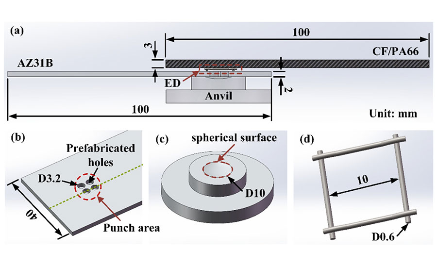
These diagrams illustrate the components of our ultrasonic extruded weld-riveting process: (a) schematic diagram of the lap joint; (b) a magnesium coupon with four holes; (c) anvil with a spherical concave zone; (d) a grid-type energy director. Source: Tianjin University
The problem with this method is that the heat can adversely affect the metal part, especially for metals with poor high-temperature resistance, such as magnesium alloys.
We have developed a new technique, ultrasonic extruded weld-riveting, that shows promise for joining metal to CFRTP without a third component and without damaging either part. In our method, prefabricated through-holes are machined on the metal part. The CFRTP part is placed on top of the metal one. Ultrasonic welding is used to melt the CFRTP, and the molten plastic is squeezed into the holes in the metal. A riveted joint will then form after the plastic cools and solidifies.
In our method, the metal sheet is not directly heated, which avoids changing the properties of the material. Our method can be used with all common metals.
To test our method, we used it to join a flat coupon of AZ31B magnesium alloy to a flat coupon of carbon fiber-reinforced polyamide (CF/PA66). Our goal was to analyze the factors affecting joint formation and the tensile shear strength of the assemblies.
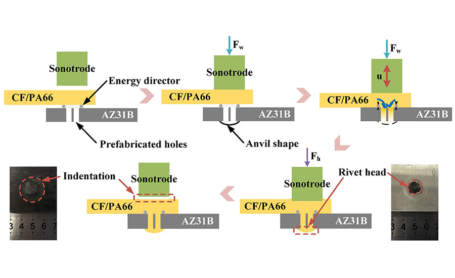
This diagram shows the ultrasonic extruded weld-riveting process. “Fw” is the welding force; “Fh” is the holding force. Source: Tianjin University
The Process
The coupons were 100 millimeters long and 40 millimeters wide. The magnesium coupon was 2 millimeters thick. The CF/PA66 coupon was 3 millimeters thick.
Four through-holes with a diameter of 3.2 millimeters were punched in the magnesium coupon near the center line. The size and distribution of the holes was determined from a preliminary study. The more holes there are, the better the joint strength will be. For this study, the number of holes was a compromise between joint performance and pretreatment workload.
A commercially available grid-type energy director made of stainless steel was used to promote heat generation at the joint interface. Measuring 10 by 10 millimeters, the energy director was slightly embedded in the surface of the CF/PA66 coupon prior to welding.
To assemble the coupons, we used an ultrasonic welder that can control welding energy, amplitude, welding force, trigger force, and other parameters. The maximum peak-to-peak amplitude was 80 microns. The coupons were joined using the welder’s energy mode—welding stops when output energy reaches a set value.
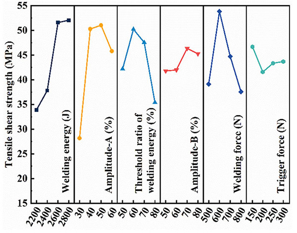
This graph shows the effect of various process parameters on the tensile strength of the joint. Source: Tianjin University
The magnesium coupon was placed on the anvil, and the CF/PA66 coupon was placed on top with the energy director facing down. The coupons were then held by a clamping system.
The anvil features a spherical concave area with curvature radius of 16 millimeters and diameter of 10 millimeters. The concave area was mainly designed to improve the bearing capacity of the joint in the direction of thickness.

This graph shows the effect of various process parameters on how well the holes in the metal part are filled. Source: Tianjin University
At the start of the process, the sonotrode applies force to the CF/PA66 coupon. When the force reaches a preset level, the sonotrode starts to vibrate perpendicular to the workpieces at a frequency of 20 kilohertz. The force subsequently increases to the preset welding force. Under the combined action of friction heat, viscoelastic heat and the welding force, the polymer matrix melts rapidly and flows into the holes in the metal part and the spherical concave area on the anvil. The vibration stops when the output energy of the welder reaches the preset welding energy. The sonotrode then applies a holding force to the parts for a set time, and the assembly is complete.
The joining mechanism of this method is based on the mechanical interlocking formed by a rivet structure. It is worth noting that due to the flow of the polymer matrix into to the holes, the sonotrode will be pressed into the composite at some depth to form an indentation. This depth is approximately equal to the total volume of the four holes divided by the tip area of the sonotrode. This indentation did not adversely affect the strength of the joint.
From our preliminary study, we learned that it was fairly easy for the composite to fill the holes, but difficult for it to enter the rivet head (the concave area on the anvil). This is due to the decrease of heat generation in the material system at the end of welding.
We found that using stepped amplitude—that is, dividing the welding process into two stages in which the amplitude in the second stage (amplitude B) is higher than that in the first stage (amplitude A)—effectively increases heat generation in the later stage of welding, enabling the molten plastic to better flow into the rivet head. Therefore, the total welding energy was considered as one factor affecting weld quality. The other parameters are welding force and trigger force.
The Experiment
With the process established, we then conducted Taguchi experiments with six factors and four levels to analyze the effects of various welding parameters on the formation and strength of the joints. The holding force was the same as the welding force, with a holding time of 3 seconds.
The tensile shear tests were conducted using a universal testing machine under a crosshead speed of 2 millimeters per minute. Tensile shear strength was calculated by dividing the tensile shear force by the total area of the four holes. Each set of parameters was tested three times, and the results were averaged. The cross-sections and fracture morphologies of the joints were observed using a microscope and a scanning electron microscope.
Based on our data, the most important parameter affecting tensile strength was amplitude A. The other parameters, in descending order, were welding energy, welding force, threshold ratio of welding energy, amplitude B and trigger force.
In addition to tensile strength, we also looked at how well the plastic filled the holes and the concave area on the anvil to make a rivet. Once again, the most important parameter was amplitude A. The other parameters, in descending order, were amplitude B, welding force, trigger force, threshold ratio of welding energy, and welding energy.
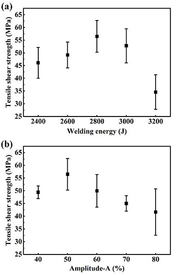
These graphs show the differences in tensile strength when a single variable is changed, and all others are held constant. (a) Welding energy is the variable, while amplitude A is fixed at 50 percent. (b) Amplitude A is the variable, while the welding energy is fixed at 2,800 joules. Source: Tianjin University
Welding energy has the most significant effect on tensile strength, but little effect on filling performance. Amplitude A has a significant effect on both joint strength and filling ability, but amplitude B has a greater effect on filling ability. The threshold ratio of welding energy has a greater impact on joint strength. The optimized welding forces for tensile strength and filling performance are the same. The trigger force plays a more important role on filling performance than tensile strength.
Since welding energy and amplitude A have the greatest impact on the weld quality, we isolated each variable for further testing. We found that tensile strength increases first and then decreases with increasing welding energy. Similarly, tensile strength increases first and then decreases with the rise of amplitude A. When amplitude A reaches 80 percent, the strength of the joint becomes unstable. The highest joint strength, 56.5 megapascals (MPa), was obtained at a welding energy of 2,800 joules and an amplitude A of 50 percent.
This is much better than other methods of joining metal and CFRTP. For example, the tensile strength of most welded joints was only about 5 to 10 MPa. Joints produced with friction self-piercing riveting have a tensile strength of 27 MPa. Joints produced with laser riveting were also less strong.
Cross-Sectional Analysis
Cross-sectional analysis of our joints revealed some interesting results. At a weld energy of 2,400 joules, we found a large amount of tiny voids in the center of the joint. These voids were caused by the insufficiency of filling.
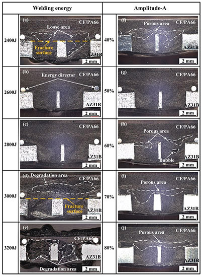
These images show the cross-sectional microstructure of the joints at different parameters: (a–e) welding energies of 2,400 to 3,200 joules, with amplitude A fixed at 50 percent; (f–j) amplitude A ranges from 40 to 80 percent, and welding energy is fixed at 2,800 joules. Source: Tianjin University
When the welding energy reached 2,600 and 2,800 joules, the joints were well-filled and had no obvious defects. When the energy reached 3,000 joules, the polymer matrix degraded, creating voids. These voids are larger and smoother than those caused by poor filling. When the energy reached 3,200 joules, the polymer matrix underwent severe degradation, and a large number of voids appeared in the joint. The thickness of the CF/PA66 in the welded area was also severely reduced.
The amplitude A setting also affected joint formation. Porous areas appeared in the joints at different amplitude A values, except the 50 percent value. Defects of similar size were observed at several levels, indicating that the formation of defects is actually more related to energy than the amplitude A value.
Contact between the fibers and the resin is not strong when amplitude A is 40 percent, which may affect the material’s strength. However, phenomenon is improved when amplitude A reaches 60 percent.
Looking at the distribution of carbon fibers in the joint also provides insight into the process. The composite near the energy director flowed along the sidewall into the holes during welding. The composite in the middle of the hole flowed downward in an arc shape. Meanwhile, composite backflow occurred in the lower part of the hole.

This image shows the typical distribution of carbon fibers in a joint when the welding energy is 2,600 joules and amplitude A is 50 percent. Source: Tianjin University
The hole-filling process of the composite can be deduced from the fiber distribution. With amplitude A vibration, since more heat is generated at the energy director, the polymer matrix in this zone is more prone to softening and melting. At the beginning, the energy director is pressed into the softened polymer matrix due to heat and welding force. The polymer matrix near the energy director melts first and flows into the holes. At the next stage, all the polymer matrix in the joint area melts and flows.
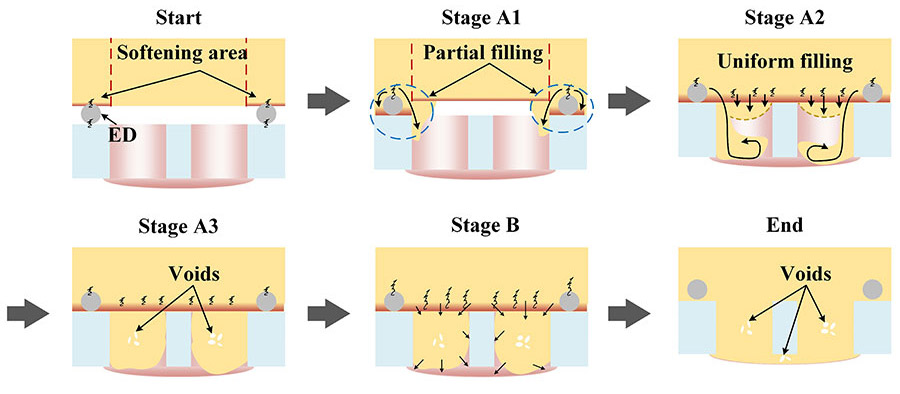
This illustration shows the hole-filling processing during the ultrasonic extruded weld-riveting. Source: Tianjin University
The composite near the energy director continues to flow along the sidewall into the holes and then forms a reflux when it reaches the bottom of the hole, while the composite in the rest of the hole flows down forming an arc-shaped surface. Finally, the holes are completely filled with composite. Defects are easily formed in the center of the holes, since those are filled last.
When the energy is relatively low, it is understandable that there is less uniform filling and more significant partial filling. More material will fill the holes along the sidewalls with less flow during uniform filling, which leads to defects close to the interface. When the energy is appropriate, the effect of uniform filling is balanced with partial filling, and this results in fewer defects. Therefore, we can assume that the greater amplitude B promotes the fluidity of the composite, leading to the formation of a strong rivet head.
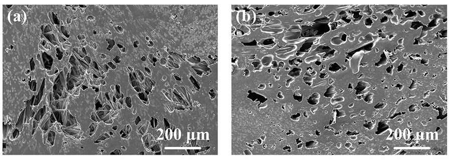
These images show the typical morphologies of defective areas: (a) loose area at 2,400 joules, 50 percent amplitude A; (b) degradation at 3,000 joules, 50 percent amplitude A. Source: Tianjin University
For the highest strength joints, the optimal parameters were as follows:
- Welding energy, 2,800 joules.
- Amplitude A, 50 percent.
- Threshold ratio of welding energy, 60 percent.
- Amplitude B, 70 percent.
- Welding force, 600 newtons.
- Trigger force, 200 newtons.
Insufficient or excessive heat input will introduce porous areas inside the joint, causing the joints to fracture along the porous areas. With optimal welding parameters, the joints fail through debonding of the fiber matrix.
For more information on assembling composites, read these articles:
Cirrus Soars With Composites
Ultrasonic Welding of Thermoplastic Composites
Composite Joining: Adhesive Pros and Cons
Looking for a reprint of this article?
From high-res PDFs to custom plaques, order your copy today!


