Part Design for Ultrasonic Welding
Ultrasonic welding offers many advantages when parts are too complex to be molded as one piece, learn how to use it to manufacture joints.

Ultrasonic energy has been used to join thermo-plastics for over 35 years. Ultrasonic welding of thermoplastic materials is by far the most common form of ultrasonic assembly, and is used extensively in all major industries including appliance, electronic and medical.
It offers advantages in speed, economy and efficiency, and is frequently chosen when parts are too complex or expensive to be molded in one piece.
There are available guidelines to aid the designer during the initial concept stage of a new product design, ensuring optimum production results. One source is Branson Ultrasonics. Its guidelines suggest that the dimensions given in the designs should be used as guidelines only, since the specifics of specific applications may require variations.
Primary Factors Influencing Joint Design
Basic questions must be answered prior to the design stage to gain a total understanding of what the weld joint must do:
- What type of material(s) is to be used?
- What is the overall part size and configuration?
-
What are the final requirements of the part?
- Is a structural bond desired?
- If so, what loads does it need to resist?
- Is a hermetic seal required?
- If so, to what pressure?
- Does the assembly require a visually attractive appearance?
- Is flash or particulate objectionable inside and/or outside?
Three Major Joint Design Characteristics
In order to obtain acceptable, repeatable welded joints, three general design guidelines must be followed:
The initial contact area between the mating surfaces should be small to concentrate and decrease the total energy (and thus the time) needed to start and complete melting. Minimizing the time the vibrating horn remains in contact with the part also reduces the potential for scuffing, and since less material is moved, less flash is generated.
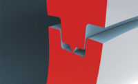
A means for aligning the mating parts should be provided. Features such as pins and sockets, steps, or tongues and grooves, should be used for alignment rather than the vibrating horn and/or fixture, to ensure proper, repeatable alignment and to avoid marking.
Horn contact directly over the joint area should be accommodated in order to transmit the mechanical energy to the joint area, while reducing the propensity for part marking.
Two Major Types of Joint Design
There are two major types of joint design: the energy director and the shear joint.
All other joint variations can be classified under these general categories or as hybrids combining aspects of both.
Energy Director
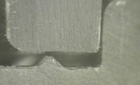
The energy director is typically a raised triangular bead of material molded on one of the joint surfaces. The primary function of the energy director is to concentrate the energy to rapidly initiate the softening and melting of the joining surface. There are vendor provided time-temperature curves for a butt joint and the more ideal joint incorporating an energy director.
The energy director permits rapid welding while achieving maximum strength; material within the director generally flows throughout the joint area. The energy director is the most commonly-used design for amorphous materials, although it is also used for semi-crystalline materials.
Butt Joint with Energy Director — It is very important to remember that the size and location of the energy director on the joint interface are dependent upon:
- Material(s).
- Requirements of the application.
- Part size.
The peak of the energy director should be as sharp as possible; energy directors that are round or flat at their peak will not flow as efficiently.
In the case of semi-crystalline resins with an energy director, the maximum joint strength is generally obtained only from the width of the base of the energy director.
Although the energy director can be located on either half of the part, it is generally included on the part contacted by the horn. In special situations (as in combinations of different materials), the general practice is to place the energy director on the part with the material that has the highest melt temperature and stiffness.
The energy director design requires a means of alignment such as pins and sockets, aligning ribs, or tongue and groove designs. Ejector pins should not be placed in the weld area.
Shear Joint
An energy director type of joint design in some cases may not produce the desired results with certain semi-crystalline resins. This is due to the fact that semi-crystalline resins change rapidly from a solid to a molten state, and back again, over a relatively narrow temperature range.
The molten material flowing from an energy director, therefore, could re-solidify before fusing with the adjoining interface. The weld strength in a semi-crystalline resin could be limited to the base width of the energy director. A shear joint configuration is recommended for these resins where geometry permits.
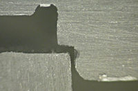
With a shear joint design, welding is accomplished by first melting the small, initial contact area and then continuing to melt with a controlled interference along the vertical walls as the parts telescope together. This allows a strong structural or hermetic seal to be obtained as the molten area of the interface is never allowed to come in contact with the surrounding air. For this reason, the shear joint is especially useful for semi-crystalline resins.
The strength of the welded joint is a function of the vertical dimension of meltdown of the joint (depth of weld), which can be adjusted to meet the requirements of the application. The general guideline for depth of weld is to use 0.75X the wall thickness.
In order for a shear joint to be successful, the following conditions must be met:
- The shear joint requires rigid side wall support to prevent deflection during welding. The walls of the bottom section must be supported at the joint by the holding fixture, which conforms closely to the outside configuration of the part.
- The top part should be of sufficient structural integrity to withstand internal deflection. Similarly, the minimum wall thickness of the bottom part should be 0.080 inch (2.00 mm) to prevent buckling.
- The surfaces creating the interference between the top and bottom parts should be flat and at 90° from each other.
A shear joint is not recommended:
- For parts with a maximum dimension of 3.0 inch.
- Parts with sharp corners, or irregular shapes. This is due to difficulty in holding the molding tolerances necessary to obtain consistent results.
Source: appliance DESIGN
Looking for a reprint of this article?
From high-res PDFs to custom plaques, order your copy today!


