Joining Wire to Small Metal Parts
State-of-the-art welding and soldering equipment ensure that wires are securely joined to terminals or other wires.

Since the early 1980s, ultrasonics has been used for wire splicing and to weld wires to metal connectors and terminals. Photo courtesy Emerson, showing Branson Ultrasonics Metal Welding technology

Ultrasonic welding effectively splices stranded (top) and tinned wire. Photo courtesy Sonobond Ultrasonics Inc.

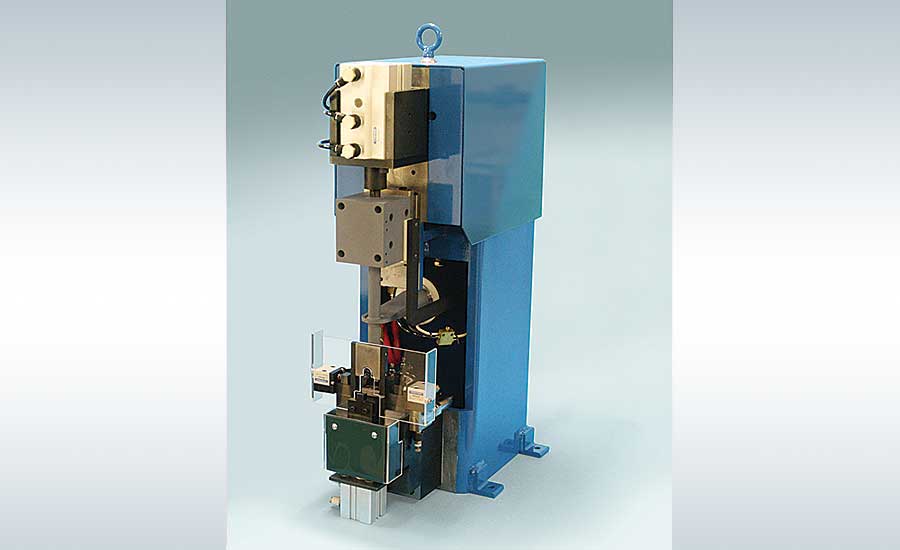
The SPG 2600 welder ultrasonically welds wire bundles of up to 20 square millimeters to a single terminal. Photo courtesy Sonobond Ultrasonics Inc.


When the average person opens up a refrigerator and grabs a too-warm soda can or bottle, his initial reaction is one of disappointment. But, if that person is an assembler of harnesses for this type of appliance, his initial thought is: Check the evaporator fan wiring harness. While inspecting it for wear and damage, he’ll also learn whether the wires were welded or soldered to connectors, and how well either process was performed.
More than likely, he’ll see that the wires are ultrasonically welded. Harness makers that serve the white goods market increasingly prefer this technology because it produces reliable connections with high conductivity.
This is not to say that all such harness makers have made the switch to ultrasonic welding. Many still prefer resistance welding and soldering. The former is economical and able to join similar and dissimilar materials, while the latter remains popular for terminating tin-plated wire and for low-volume production.
What manufacturers know for sure is that all three methods are effective at joining wires to metal parts, as well as splicing two or more wires together. They also know that fully understanding all the pros and cons of each technology is essential to selecting the best joining process for an application.
Ultrasonic Welding
Since the early 1980s, ultrasonics has been used for wire splicing and to weld wires to metal connectors and terminals. The process involves vibrating wire strands together under pressure at a frequency of 15 to 40 kilohertz. The vibrational energy disperses surface oxides to create a galling on the strands and form a solid-state metallurgical bond.
“The ultrasonic process provides a low resistance weld,” notes Joe Stacy, employed by Emerson as national sales manager for Branson Ultrasonics Metal Welding, Americas. “And a low resistance weld allows for the use of smaller cables, which saves manufacturers money and space.”
Typically, conductive materials like aluminum, nickel, silver, copper and gold are ultrasonically welded. The process consumes about 80 percent less energy than resistance welding and it does not require water cooling. And, unlike soldering, ultrasonic welding doesn’t require flux or filler materials.
The 2032S system from Branson produces high-quality wire splices in a cross-sectional area of 0.7 to 40 square millimeters. Equipped with a Versagraphic power supply, the system automatically and instantly adjusts splice parameters, including width, pressure, amplitude and energy. Operators
can program a preset number of splices in sequence for optimum production efficiency. Other standard features include a retractable anvil (to maximize wire load area), a gather tool (for easy splice removal), and cooling air to increase tool life in high-production environments.
“Regardless of the industries they serve, harness makers need welders that are reliable and cost effective 24-7,” says Stacy. “Ultrasonic welding is consistently cost effective, and this is one of the main reasons for its growing popularity.”
Janet Devine, president of Sonobond Ultrasonics Inc., says evolving machine technology also helps ultrasonic welding maintain its economic and efficiency advantages over other joining methods. Ceramic piezoelectric transducers, for example, are able to operate efficiently at high voltage and high temperature (up to 300 C). In addition, the power supply and electronics offer digital precision and control.
Sonobond’s SPG (single point ground) 2600 welder ultrasonically welds wire bundles of up to 20 square millimeters (18 wires maximum) to a single terminal. The microprocessor-controlled unit accomplishes the weld in one pulse before automatically folding the terminal arms to provide stress relief on the joint. It handles standard and lightly tinned or oxidized wires.
Devine says the welder features a patented Wedge-Reed system instead of a lateral drive system. The former combines low vibratory amplitude with high vibratory force directed in a shear mode parallel to the interface of the materials being welded. This produces a much better impedance match to a metal weldment, which is six to nine times more dense than plastics.
Despite numerous benefits, ultrasonic welding does have some limitations. For starters, the process takes longer than crimping (about 2 seconds), and the equipment is relatively expensive ($35,000 to $70,000). It cannot be used with tin plating, wire bundles smaller than 1 square millimeter, thin individual wires (36 AWG and higher) or those with a high strand count. In addition, because the process requires an overlap, butt joints are not always possible.
Resistance Welding
Like ultrasonic welding, resistance welding has a long track record of quickly and cost-effectively joining wire to small metal parts. Where they differ is resistance welding is better suited for less-conductive materials like nickel and stainless steel. The process would be used, for example, if the terminal is tin-plated brass.
In resistance welding, a wire is inserted into a hole or other type of self-fixturing terminal design. The wire and other part are then pushed together while an electrical current is briefly passed through them. Resistance to the current generates the heat for welding, both within and between the part and wire. When the current stops, the electrodes continue to hold the parts together to form a weld.
Resistance welding is typically used for splicing and compacting stranded copper wires. The process occurs within 2 to 50 milliseconds, depending on wire size (50 to 10 AWG). Its other benefits are energy efficiency, clean welds and a minimum heat-affected zone, where weld heat barely alters material at or near the weld.
On the downside, heat generated during resistance welding can anneal the wire, which can reduce the tensile strength of the wire strands adjacent to the weld. Electrode wear is also high, due to the current density.
“The key to successfully resistance welding stranded copper wire to different kinds of terminals is preventing it from spreading out during welding,” explains David Steinmeier, founder and president of microJoining Solutions (mJS), a consulting company. Since 1998, mJS has specialized in laser and resistance welding process development, optimization and validation. “Any and all wire strands that spread past the joint can short out nearby connectors.”
Steinmeier offers four methods to capture these strands. The first is electrical solidification, which involves solidifying the stranded wire into a solid copper block by passing a high electrical current through the block via top and bottom tungsten electrodes. Force on the top electrode helps compress and solidify the stranded wire. The solid block is then welded to the terminal.
Another option is making a V-shaped groove or one-half-diameter arc on the electrode tip, and then placing the strands within this area during welding. This method may not capture and weld all strands, plus it presents the challenge of cleaning and maintaining the tip, and the possibility of the top electrode shorting out against the bottom one and terminating the welding process.
The pig tail insulation method involves separating, but not removing, insulation from the wire (to reduce wiring spreading during welding) and contacting the exposed wire strands with a flat rectangular top electrode. A final option is to design your fixture with guideposts or retaining pins that hold the stranded wire over the terminal and prevent the strands from spreading during welding. This design can accommodate one or more terminals.
“Aluminum wire can be resistance welded, but it is a challenge,” notes Marty Mewborne, sales engineering manager at Amada Miyachi America. “The problem is the top layer oxidizes and the wire quickly weakens.”
To overcome the problem, Mewborne recommends harness makers use copper terminals with aluminum cladding on the end. These terminals enable an aluminum-to-aluminum weld.
Hot Crimping
For decades, European electric-motor manufacturers Bosch, Siemens and Volkswagen used machines or chemicals to strip the enamel coating off the ends of magnet wires before crimping them to copper ring terminals or sleeves. Strunk Connect GmbH & Co. KG changed all that in 2010 with the introduction of hot crimping, a technology that vaporizes the insulation during crimping of the wire and terminal or sleeve. Besides increasing manufacturers’ productivity, the technology improves weld strength by minimizing stress on the copper in the wire and terminal.
Similar to resistance welding, hot crimping relies on heat generated by the electrical resistance of the material being welded and the force used to hold the materials together during welding. Unlike resistance welding, hot crimping uses specially designed welding heads that join the wire to the terminal with nearly zero contact resistance.
Heinz Bockard, managing director of Strunk Connect, says the technology can join standard and high-frequency (current above 10 kilohertz) magnet wire and uninsulated copper wires. Magnet wire is made of copper or aluminum and coated with a very thin layer of enamel or polymer insulation. Hot crimping can weld wire diameters from 30 AWG up to 300 MCM (300,000 circular mils).
On a semiautomatic benchtop machine, a worker places the coil wound with magnet wire into the machine, inserts open wire ends in the terminal and activates the weld cycle. Within milliseconds, the welding heads release enough current to produce a temperature of about 700 C at the terminal, vaporizing the insulation and welding the wire ends to each other and the terminal. Over the next several seconds, the terminal cools down to 100 C and then 45 C before it is manually removed from the machine.
Semiautomated systems have a small pallet that moves the component into and out of the hot-crimping machine. The worker inserts the wire ends into the terminal, activates the machine and removes the component from the pallet after it cools. Fully automated systems also automate the insertion of wire ends into the terminal prior to welding.
Soldering
Assemblers have used soldering to weld and splice wire for more than a century, which is relatively new for a technology that has been around since 3,000 BC. Soldering is the process of joining two pieces of metal with a filler metal (solder) that has a melting point (approximately 200 C) lower than the workpiece.
Because it is primarily done manually, soldering is best suited for low-volume production. In some high-volume applications, however, hand soldering is unavoidable. Examples include connecting wires to a specialty device where a splice is impossible, or soldering a high-end coaxial cable to a connector.
The process has several advantages and disadvantages. On the plus side, soldering offers durability, corrosion-resistance, relatively inexpensive equipment, and the flexibility of making connections that can be easily removed, thereby simplifying prototyping and fieldwork. Negatives include safety concerns (hot irons and molten metal on the production floor), corrosive flux and the need for extractors to remove fumes from burned flux.
“Flash soldering of wire to terminals is starting to appear in applications where it is not possible to apply resistance welding electrodes to the wire-terminal joint,” claims Steinmeier. “This automated method involves the use of diode lasers, and takes from 0.1 to 0.25 second, compared with about 2 seconds for hand soldering.”
According to Steinmeier, flash soldering is designed to terminate or splice tiny wire: 15 to 125 microns wide (50 to 36 AWG). It uses standard or no-lead solder (melting point of 80 C to 220 C), and is preferred for applications involving tiny, sensitive connectors or PCBs, such as those in medical devices.
The technology is also flexible. Steinmeier says a hot air pen can be used in place of a laser. Pre-soldered terminals are another option. After the wire is crimped in the terminal, it is passed in front of the pen so the solder melts and flows in place.
Looking for a reprint of this article?
From high-res PDFs to custom plaques, order your copy today!


