Vibratory Bowl Feeders for Automated Assembly

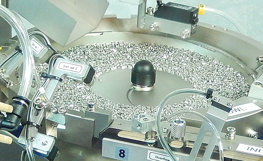
Vibratory bowls feed a wide range of metal and plastic parts, including screws, nuts, pins, dowels, caps, plugs, lightbulb filaments, threaded inserts and other fasteners. Photo courtesy Mirai Inter-Technologies Systems Ltd.

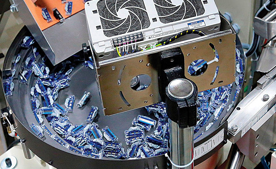
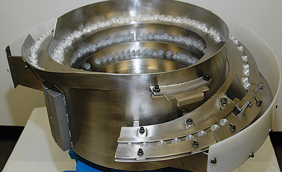
This inside-tooling (cascade) bowl feeds components for a disposable consumer product. Photo courtesy Arthur G. Russell Co. Inc.

Bowls featuring outside tooling have a straight-wall design. Parts ride inside tracking to the top of the bowl where they are captured for proper orientation. Photo courtesy Homer City Automation


Depending on how it’s interpreted, a question can have more than one correct answer. For example, consider the question: What is the state of vibratory bowl feeders used in automated assembly?
Some manufacturers may answer “Indiana,” because more vibratory bowl suppliers are, or have been, headquartered in that state than anywhere else in the country since the early 1950s. Others, however, may interpret the word ‘state’ to mean economic market condition, and reply, “very strong.” They, too, would be correct.
“The market for vibratory bowl feeders is vibrant and continues to increase to keep pace with growing production demands,” notes Greg Pflum, president of Performance Feeders Inc. “One major reason for this is manufacturers that have reshored know it’s necessary to automate assembly and minimize production costs.”
Although based in Florida now, Performance Feeders was originally headquartered in the Indianapolis area in the early 1970s and stayed there until 2007. The supplier builds feeder bowls for OEMs and Tier 1s in the automotive, medical, aerospace, white goods and consumer products industries.
Last year, it designed a complex single-bowl vibratory feed system for a medical device manufacturer. The bowl orients three styles of cylindrical plastic parts so the open cup end is facing up. Parts are fed out of the bowl in four lines, which merge into two lines and then move onto a 10-line vibratory track that accumulates hundreds of parts before releasing them for further assembly.
Measuring 30 inches in diameter, the bowl features outside tooling that feeds 300 parts per minute. Pflum says the bowl is specifically designed to prevent parts from lodging in cavities and being left in the bowl when changing the style of part being fed.
Vibratory bowl feeders also work extremely well in simple automated applications, such as orienting one type of part and feeding it to a robot, feed tube or other equipment. This flexibility is the main reason feeder bowls are so often used to singulate and orient bulk parts. Simple operation is another reason, although there are several tips, techniques and best practices manufacturers can implement to optimize performance on a daily basis.
Two Types
Vibratory bowl feeders are categorized according to the location of their feed tooling. Inside-tooling bowls have a cascade or conical (like a wok) shape, the latter being much more common in Europe. Bowls featuring outside tooling have a straight-wall design. The tooling is made of metal and TIG welded or bolted to the bowl, depending on its material, size and the part being fed.
Bowls measure 3 to 60 inches in diameter; are cast of durable plastic or aluminum and milled, or fabricated from steel or stainless steel. They are usually custom tooled to orient and feed a specific part or set of parts. Because of this, manual bowl building is “not science but truly a black art that must be learned through experience,” claims Ron Merle, applications manager for Homer City Automation.
During operation, a hopper, elevator or prefeeder dumps parts into the bowl, which sits upon a vibrating drive unit. The amplitude of the vibrations is governed by a nearby controller. When the drive unit is turned on, it vibrates the bowl and forces parts onto either inside tooling (within cascade bowls) or narrow inclined tracks (in straight-wall bowls).
Parts not correctly oriented by a certain point on the inside tooling are dropped back onto the lower section of the tooling and recirculated. In contrast, parts in straightwall bowls ride the tracking to the top of the bowl where they are captured for proper orientation. Parts improperly oriented there are blown into a return pan for recirculation.
Working vibratory feeder bowls produce an average noise level from 90 to 100 decibels. This volume is equivalent to a circular saw cutting through lumber.
According to Merle, vibratory bowls feed a wide range of metal and plastic parts, including nails, screws, nuts, pins, dowels, caps, impact and self-piercing rivets, clips, plugs, rings, light bulb filaments, threaded inserts, self-clinching fasteners and other parts.
Cascade bowls are more often used for feeding simple to moderately complex parts (such as headed items) because they have a limited tooling area. Outside track bowls are preferred for orienting more complex parts.
Advancing Outside the Bowl
Interestingly, vibratory feeders have been a victim of their own success. The technology has worked so well, for so long, that innovation in bowl design and function hasn’t been necessary. However, some advancements have appeared over the last decade or so related to other feeder system components.
Traditionally, feeder drives have relied on electromagnetic coils to vibrate bowls. But, that is no longer the only option. For the last several years, Mirai Inter-Technologies Systems Ltd. has distributed Sanki drives featuring piezoelectric resonators made of fine ceramic (lead titanate and lead zirconate).
“We’ve raised the awareness of many manufacturers in North America about the benefits of this technology from Japan,” says Nathan Scott, manager of engineering and distribution for Mirai. “More than 90 percent of the feeder systems we build now feature piezoelectric drives.”
Because piezoelectric feeders are driven directly by leaf springs that oscillate at a high rate, they can feed small, thin parts without jiggling. Scott says piezoelectric feeders consume 70 percent less energy than electromagnetic feeders, are unaffected by ambient conditions, and do not generate heat. In addition, the drive spring does not require adjustment. Once the tooling is complete, the feeders are tuned digitally with no need to adjust the drive springs. The controllers adapt to 50 or 60 hertz automatically.
Afag Automation Inc. makes electromagnetic coil drives, but theyoperate on a counter vibration principal known as reactive force compensation. Sean McBride, national sales manager for Afag, says this technology prevents transmission of vibration to connecting linear feeders, enablingthem to be mounted in very close tolerance next to the bowl.
Without the need for a rubber buffer, linear feeders are more precisely positioned at the bowl exit and near escapement devices. The technology also enables the feeding of parts with complex geometry.
Another important feeder system component is the controller,whichreleases a timed pulse of current from the power line through the drive coils to create vibration. The controller needs to be tuned so its pulse frequency per second matches that of the power line: 60 hertz in North America and 50 hertz in Europe and most of Asia.
VibroBlock controllers from Arthur G. Russell Co. Inc. are self-tuning. State-of-the-art electronics within the controller vary energy pulse duration to the drive automatically and ever so slightly, resulting in tight control of amplitude and efficient bowl operation, says Bill Mis, vice president of sales for Arthur G. Russell.
“As a bowl empties and gets lighter, parts will often start jumping much more wildly than when the bowl was full,” explains Doug Daubenspeck, a project engineer for 26 years with Vibromatic Co. Inc. “In the past, the operator’s only options would have been to either manually lower the vibration frequency or add more parts.”
Today, though, manufacturers use a digital controller in their feeding system to ensure consistent frequency. With the MFS series (made by the German company REO), an operator inputs a frequency set point and the controller maintains it regardless of how many parts are inside the feeder bowl. Vibromatic has been selling the controller since 2001.
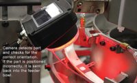
Another area where technology has advanced and enabled assemblers to dramatically improve the parts positioning process is machine vision. Cameras and vision sensors are faster, more accurate and cheaper than ever. What’s more, they greatly increase the flexibility of feeder bowl systems to handle parts of various sizes and shapes.
As a result, vision systems are regularly integrated into bowl tooling, points out Gary Marsh, executive vice president of sales for Shibuya Hoppmann Corp. Cameras accurately verify part orientation at the bowl exit, while
sensors often monitor various areas of the bowl to automatically trigger the prefeeder or hopper to keep parts at an optimal level for bowl operation. Photoelectric sensors may even be used to turn bowl feeders off when an operator is absent or part levels are too low.
Many Ways to Better Feeding
Although vibratory bowls are usually tooled to only feed a specific robust part, there are several ways to increase their flexibility. To feed fragile parts, the bowl surface (inside and outside) can be lined with urethane, rubber, Teflon or polyurethane. Dave Goodenough, director of robot technology development for Edgewater Automation, says that this lining also lessens noise.
Parts should always be clean and dry, regardless of size or material, recommends McBride. Manufacturers also need to make sure that the types of parts used in the final test run are the same as those that will be used in real-world production. If they differ, the supplier may not be providing the optimum bowl design.
When it comes to proper feeder operation, rely more on your supplier unless the operator has extensive experience or training. McBride also suggests giving line supervisors and technicians more control access to the feeders than operators.
It’s also a good idea to establish and stick to a regular cleaning and maintenance schedule. This might include carefully wiping down or using air to blow out all bowl areas to remove any dust and debris. Feeders that handle parts with a coating on them definitely need extra cleaning, says McBride.
“Always strive for consistent feeder performance,” says Scott. “If the feeder runs good in the morning but poorly later in the day, it could be that the electromagnetic coils are overly affected by the temperature, voltage or frequency differences on the assembly line. Using a piezoelectric drive may solve this problem.”
Make sure the clearance of contained sections is the proper height. Scott says that too little or too much is to be avoided. Enough clearance is that which allows parts to move forward (under vibration) without jamming between the tracks.
When feeding sensitive electronic components, such as chip capacitors, chip resistors and connectors, Scott recommends using piezoelectric feeders. The reason is these feeders vibrate with higher frequency and lower amplitude.
“A feeder bowl is for feeding parts, not storing them,” says Merle. “Do not design your system so the operator merely dumps parts and leaves until the bowl is nearly empty. Rely on the prefeeder or hopper for that. Overfilling a bowl causes frequent jamming, but, too few parts will cause an inadequate feed rate output.”
Whenever possible, manufacturers should get feeder suppliers involved in part design. Doing this eliminates the costly and time-consuming problem of making certain parts more feeder-friendly after the fact. Examples, according to Merle, include 3D parts that might require a tab added to them or asymmetrical parts that need to be made more symmetrical.
Daubenspeck notes the importance of keeping the feeder drive tuned. When it’s improperly tuned, coils are over or under-sprung and coil tension does not correspond with the natural frequency of the feeder mass. Either condition prevents the feeder mass from returning to its neutral position before the next pulse occurs within 0.5 second. Normal 60 hertz current produces 120 magnetic cycles per second and transmits it to the bowl.
“Be aware that the quality of the parts you feed may change over time,” says Pflum. “Parts formed with a new die may have no burrs, but, years later, as the die wears, burrs may appear. Changing part suppliers can also result in getting parts that are more difficult to feed and orient.”
Looking for a reprint of this article?
From high-res PDFs to custom plaques, order your copy today!


