Round Energy Directors for Ultrasonic Welding

Dukane developed the ISTeP to provide a test specimen with changeable joint designs for ultrasonic welding. Photo courtesy Dukane Corp.

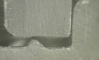
This image shows a cross-section an ISTeP part prior to welding. Note the 90-degree energy director. Photo courtesy Dukane Corp.

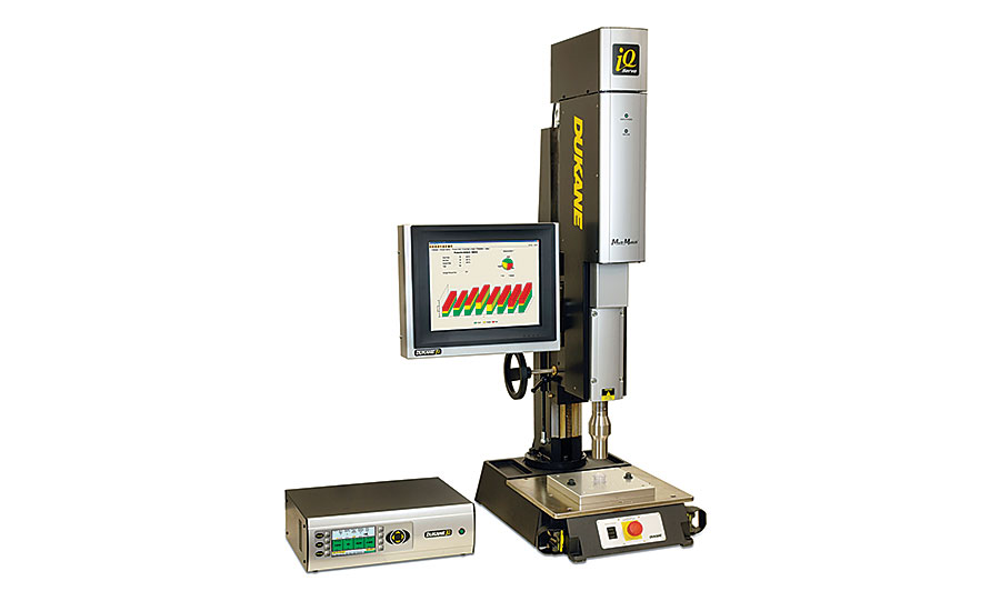
Experiments were conducted using a Dukane 30-kilohertz IQ Servo ultrasonic welder with Melt-Match technology. The welder was equipped with a flat-face, high-gain horn. Photo courtesy Dukane Corp.

For pull testing, Dukane researchers used a variable-speed test stand equipped with this custom fixture. Photo courtesy Dukane Corp.

During pull testing, the breaks often occurred in the parent material rather than the welded joint, regardless of the design of the energy director. Photo courtesy Dukane Corp.

The best results in strength and consistency were achieved using a profiled weld velocity that gradually increased from 0.25 to 0.4 millimeter per second after formation of an initial melt layer at the joint interface. Note the large homogenous area at the joint interface. Photo courtesy Dukane Corp.

A part with a round energy director can be molded more consistently than a part with a sharp energy director. The mold is also less expensive to make. Photo courtesy Dukane Corp.

An round energy director requires a slightly higher amplitude to initiate melting than a part with a sharp tip. Tests revealed that an amplitude of 32 microns produced the strongest, most consistent welds. Source: Dukane Corp.

With a sharp energy director, the strongest welds were produced at an amplitude of 28 microns. Source: Dukane Corp.

Parts with a round energy director can be successfully welded with a strength and consistency matching and even exceeding parts with a sharp energy director. Source: Dukane Corp.


One of the most important factors in optimizing the ultrasonic plastic welding process is the right joint design. Parts to be welded often have a small initial contact at the joint interface to concentrate the ultrasonic energy and initiate melting.
For many applications, this small contact area is achieved with an energy director (ED), a sharply pointed triangular rib molded onto the surface of one of the parts. Because the ED is designed to provide a small pointed contact area, its size and shape—or rather the sharpness, roundness, or flatness of the tip—are critical factors for producing a good weld. The geometrical consistency of the ED, both within a single part as well as on a part-to-part basis, can significantly affect process repeatability, joint quality and weld strength.
Keeping the size and shape of the ED consistent on a part-to-part basis in high-volume, multi-cavity molding operations is a constant challenge. Dimensional variations from cavity to cavity and variations in the molding process are always present. The tip of an ED always has some roundness, because it is impossible to mold a perfectly sharp point.
Major contributors to inconsistency in ED shape are caused by unavoidable differences in the machining of different cavities; problems with venting of cavities; accumulation of debris in cavities; and aging of the cutting tools and molding equipment. As requirements for part tolerances become more stringent, these factors translate to higher costs for quality assurance and maintenance for molders.
Ensuring sharp ED details also presents an added expense in mold making. To make them as sharp as possible, electrical discharge machining is used, and that adds additional engineering, setup, and machining steps to the mold making process.
The sophistication and accuracy of modern ultrasonic welding equipment ensure a highly repeatable welding process. However, part-to-part variation in the size and shape of the ED presents a challenge in maintaining weld consistency, aesthetics and functional performance. For manufacturers of medical devices, electronics and auto parts, a more robust ED design that eliminates this source of variability in the joining process would go a long way toward meeting quality requirements and improving assembly line performance.
Experimentation
A part with round energy director would be easier to mold more consistently. The mold would also be less expensive to make. But could a round energy director make for better ultrasonic welding?
We ran a series of experiments to compare the performance of round and sharp EDs using our Industrial Standard Test Part (ISTeP). (We developed the ISTeP to provide a test specimen with changeable joint designs for ultrasonic welding.) Another goal was to further investigate the process control capabilities of servo-driven ultrasonic welders for improving the welding process. We also sought to understand the sources of variability in weld strength and find ways to control and eliminate them.
We wanted to develop a process that would generate the strongest and most repeatable weld possible for both ED designs and to understand what makes a weld strong based on analysis of the welder’s graphical output and microscopic characterization of the weld zone.
For our experiments, we used ISTeP parts with a sharp ED (a 90-degree angle) and a half-round ED (0.7-millimeter radius). The parts were molded of Lexan 121R polycarbonate.
The parts were welded with a Dukane 30-kilohertz, 1,800-watt IQ Servo ultrasonic welder with Melt-Match technology and an interface running iQ Explorer II software for data collection and analysis. The tooling was a flat-face, high-gain horn and a custom drop-in style fixture.
During our experiments, we took full advantage of the welder’s advanced control features, including Melt-Detect, which directs the press to hold its position on the assembly after initiation of welding. The press will not continue downward movement until a drop in force is detected. This drop in force indicates the presence of an initial molten layer. Control of the material displacement rate was done by regulating weld velocity. These features are significantly different from the capabilities of pneumatic welders.
For pull testing, we used a variable-speed test stand from Com-Ten
Industries with a 22,250-newton capacity and an accuracy of ±0.5 percent.
Establishing Process Settings
We conducted a full-factorial design of experiments (DOE) for both sharp and round ED parts. The initial parameters for the study were based on a study we conducted in 2012 (see “The Benefits of Servo-Driven Ultrasonic Welding,”
ASSEMBLY, November 2013).
A full-factorial DOE examines all possible combinations of a set of variables. This sort of study requires more trials and is more costly and labor-intensive than other designs, but it provides a more comprehensive evaluation of the process variables.
For the initial phase of experimentation, we conducted a three-level, three-variable (3 x 3) study. The three variables were trigger force, Melt-Detect and weld velocity. These variables had the most effect on weld strength in the earlier study.
Weld distance was set at constant value of 0.254 millimeter for both parts: one with a round ED, 0.4-millimeter tall, and one with a pointed ED, 0.38 millimeter tall. This would ensure that joint failure would occur through the weld during testing. The sample size was limited to six replications to keep the experiments to a manageable number. Welds were evaluated by tensile testing. Failure load was peak tensile force at break.
DOE Results
The DOE results show that, at a constant amplitude, the main factors affecting weld strength for both sharp and round EDs are weld velocity and trigger force. Weld velocity appears to play the most important role in the weld strength, although trigger force also has a significant effect. Higher weld strength was associated with lower weld velocity and higher trigger force, regardless of the ED shape. The effect of the Melt-Detect value in these initial trials wasn’t significant and would be investigated in further experiments.
The data related to these process parameters’ effect on weld strength consistency had a limited value in this series of experiments, since there were a relatively small number of samples in each trial. However, the purpose of this initial DOE was not to identify the “best” settings for ISTeP parts, but rather to establish a base and direction for further process refinement for joints with both types of EDs, by utilizing the capabilities of the servo-driven ultrasonic welder.
The Effect of Trigger Force
Based on the DOE results, the effect of trigger force on weld strength was significant. In the range from 178 to 356 newtons investigated in this DOE, the highest weld strength values correlate with higher trigger forces. Subsequent experimentation indicated that a trigger force of 400 newtons improved consistency of the test results for both types of ED.
The sharp ED was not damaged by a trigger force of 400 newtons. Just to be sure, we inspected the parts with a microscope after applying trigger force, but without initiating the welding cycle. No damage to the ED was observed in these parts.
The Effect of Amplitude
The welding amplitude is critical for initiating material melting at the tip of the ED at the beginning of the ultrasonic welding cycle. Because the ED is designed to concentrate ultrasonic energy, the shape of its tip—sharpness, roundness or flatness—is an important factor for a good joint. These geometrical features, as well as the specific properties of the material, dictate the optimal welding amplitude. For this reason, it was critical to identify a preliminary range of amplitudes for round EDs and investigate the effect of the amplitude setting on weld strength.
We ran a series of trials in which amplitude was varied, while the rest of the parameters stayed constant. The results indicated that weld strength increases with increased amplitude. The best results correlated with the highest value, 36 microns.
However, in a later stage, when the weld speed was further optimized, reducing the amplitude to 32 microns produced stronger and more consistent welds.
For ISTeP parts with sharp EDs, some very strong welds, some failing through the parent material, were produced at all three amplitude levels tested (28, 32 and 36 microns). However, the highest average failure load (calculated on a sample of five parts) was recorded at 28 microns. This amplitude setting was used in follow-up experiments focused on weld velocity optimization.
A round ED requires a slightly higher amplitude to initiate melting than a part with a sharp tip.
The Effect of Weld Velocity
Special attention was given to identifying the optimum weld velocity. Our DOE results and previous studies indicated that weld velocity is one of the most critical factors affecting weld strength. During the first stage of experimentation, our efforts focused on maximizing weld strength without fully collapsing the ED. Weld displacement was set at 0.254 millimeter for both designs.
Initially, a number of constant and profiled weld velocities were selected based on the DOE results and tested using five samples for each setting. Once we identified which weld velocity settings produced welds with the highest strength, the sample number was increased to 20 to assess process consistency. Finally, in the last set of trials, the sample number was increased to 30 to confirm the performance of the best settings.
The force and distance diagrams generated by the welder were analyzed for each weld and correlated to weld strength. By comparing graphs related to a strong weld and those associated with weaker ones, we were able to better understand how to control material melting and displacement during different stages of weld formation to produce a strong weld.
The effect of weld velocity on weld formation was also assessed by microscopic characterization of the weld zone. Representative welds were cross-sectioned, inspected and photographed using a microscope.
Results and Observations
The best results in strength and consistency were achieved using a profiled weld velocity that gradually increased from 0.25 to 0.4 millimeter per second after formation of an initial melt layer at the joint interface.
Application of low forces to the plastic after it begins to melt can be seen on a force and distance diagram as a distinct dip in the force curve. This phase, lasting 120 to 140 milliseconds, allows for melt propagation and a buildup of the melt layer in both types of EDs and also in the mating part. This was evident by shape of the melt zone observed under the microscope. The application of moderate forces at the later stages of the process generated a steady linear displacement rate, while preventing excessive material displacement during the weld.
A steady melt rate creates a homogenous molecular structure and a stronger weld. While the total collapse (including the cooling time) recorded for these welds was in the range of 0.274 to 0.279 millimeter, for welds with an optimized weld velocity profile, microscopic characterization of the weld zone shows that the melt formed a consistent layer proliferating into both parts, fusing them into one part along the whole interface of the assembly.
During a typical ultrasonic welding cycle, most of the plastic melting takes place in the ED body, and its molten material forms the bond. If the total weld travel (collapse) at the end of the weld cycle is less than the ED height, the ED will not melt fully, which would affect weld strength, weld tightness and appearance.
In our trials, the total weld collapse at the end of the cooling cycle was programmed to be significantly less than ED height, but the process was programmed to allow the molten material to propagate through the interface, forming a uniform melt layer between both parts. This uniform melt zone extended into both parts and was the main source of the high strength of these welds. Indeed, a significant number of the welds failed through the parent material.
The Effect of Melt-Detect
In general, we observed that the specific percentage of the force reduction necessary to confirm the presence of a melt layer at the interface of the joining parts does not have a noticeable effect on the weld strength when other process settings remain constant.
Our experiments included four settings of the Melt-Detect feature: 2 percent, 5 percent, 10 percent and “No Melt Detect.” The data showed that there was no significant difference in the average failure load between 2 percent, 5 percent and 10 percent. Weld strengths were of 5,223 newtons, 5,032 newtons and 5,118 newtons, respectively. However, the consistency of the results was better for 2 percent setting: 5.84 percent vs. 8.27 percent and 9.53 percent, respectively.
When the Melt-Detect feature was switched off, a noticeable drop in weld strength (4,585 newtons) and a higher standard deviation (14.82 percent) were recorded.
The force diagram typical for such welds also shows very different melting conditions compared to welds formed with the Melt-Detect feature, regardless of the value set. This demonstrates the benefit of controlling initial melt generation in the interface.
Round vs. Sharp EDs
Although slightly higher amplitude was needed for the round EDs (32 microns vs. 28 microns), the balance of the welding factors investigated were found to have a similar effect on weld strength for both designs of ED. The welding parameters that produced the strongest and most consistent welds were the same for both designs: trigger force at 400 newtons, Melt-Detect at 2 percent, and weld velocity profiled from 0.25 to 0.4 millimeter per second. Note that the weld distance was limited to 0.25 millimeter for both types of ED.
The best average failure load values recorded for parts with a round ED were 9 percent higher than for parts with the sharp ED: 4,766 newtons vs. 5,223 newtons. Weld strength with the round EDs was also more consistent. The standard deviation for welds with the round EDs was 5.85 percent vs. 10.59 percent for sharp EDs.
A likely explanation to the superior strength and consistency of welds of the round EDs is that this shape provides a larger amount of material to form the bond than a 90-degree ED of the same height.
While analyzing force and distance diagrams, we observed that the melt behavior of round and sharp EDs during the weld cycle appears to be different, even if the process settings are identical. Distance diagrams, which represent the rate of material displacement, are practically identical for both types of ED. However, the forces applied to achieve the programmed weld velocity and weld distance are significantly lower for the part with the round ED.
One possible explanation for this phenomenon is that the round ED, with its higher volume, accumulates more heat in its body during the Melt-Detect phase. This additional heat lowers the viscosity of the molten material resulting in a reduction of the force required to achieve the programmed velocity.
Conclusions
Our performance evaluations confirm that parts with a round ED can be successfully welded with weld strength and consistency matching and even exceeding similar parts that have a 90-degree ED.
The parameters that produced the strongest welds and best standard deviation values for both types of ED were found to be similar, with the exception of amplitude. For parts with sharp EDs, the best results were achieved with an amplitude of 28 microns, while a setting of 32 microns was best for parts with round EDs. Considering that both types of parts were made from the same material, the difference in amplitude is based on fact that a round tip of ED requires slightly higher amplitude to initiate melting than a sharp tip.
Considering that implementation of a round ED design could significantly simplify molding operations and increase part consistency, the round ED represents an attractive alternative to a sharp one.
Editor’s note: The following Dukane employees also contributed to this study: Hardik Pathak, tooling design engineer; Leo Klinstein, director of engineering; Mike Luehr, applications lab manager; Paul Golko, principal mechanical engineer, and Kenneth Holt, senior application engineer.
Looking for a reprint of this article?
From high-res PDFs to custom plaques, order your copy today!


