Choosing a Vision Interface Standard
Recently introduced USB3 Vision joins several other established standards, all of which increase component selection, simplify setup and expand the market for vision systems.

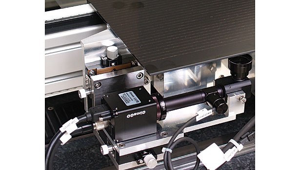
In this application, a solar-module manufacturer uses a laser to scribe patterns on thin-film solar modules. Six GigE cameras maintain process-tool calibration, determine wear status, and verify correct processing of the modules. Photo courtesy Cognex Corp.

GigE Vision-compliant cameras connect to a PC via a Gigabit Ethernet cable. Because each GigE camera has its own IP address, there is no limit to how many cameras can be operated on the same network. Photo courtesy Microscan Systems Inc.

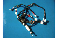
Camera Link allows the use of more than one cable per camera, such as the Piranha 4. Maximum length of each cable is 10 meters. Photo courtesy Teledyne DALSA Inc.

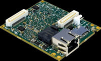
The latest interface standard from the AIA is USB3 Vision, which is based on the USB 3.0 interface—also known as SuperSpeed USB. Some suppliers already offer USB3 Vision-compliant cameras. Photo courtesy AIA


Component interoperability for PC-based vision systems has come a long way in a short time. The main reason for this quick evolution is interface standards, which the AIA, a machine vision trade group, began introducing in 2000.
In the 1980s and 1990s, digital cameras began to replace analog cameras in machine vision systems. Unfortunately, these cameras often had proprietary interfaces that required custom cables to connect to a PC. This forced end-users to either rely on a single supplier when developing a vision system, or spend lots of time and money tweaking the connections between camera, frame grabber and other components so they worked well together.
The most popular interface standard during these years was FireWire (IEEE1394-DCAM), which had the highest bandwidth at the time—200 megabits per second (Mbps). Developed by Apple Computer Inc. in 1987, FireWire was originally used to transfer large amounts of data between Mac computers for storage.
By the mid-1990s, Sony Corp. used the interface on its camcorders and laptops, verifying FireWire’s ability to quickly transfer image data. Most industrial PCs also had FireWire ports, and end-users liked that FireWire doesn’t need a frame grabber to acquire images into a PC.
Knowing all of this—and with no machine-vision standard yet available—several suppliers made cameras that met the FireWire interface standard. However, this interface standard has declined significantly in use with the introduction of AIA standards.
These industry standards expand component selection and simplify system setup. They enable end-users and integrators to create vision systems using products from one or more suppliers, while ensuring interoperability among components that meet the same interface standard.
“An interface standard codifies how a camera is connected to a computer, so that all who implement the interface do it in the same way,” says Bob McCurrach, director of standards development for the AIA. “The standard shrinks the amount of knowledge end-users and integrators must master to use the vision technology efficiently and effectively. It also lowers system cost and expands the market of vision system applications.”
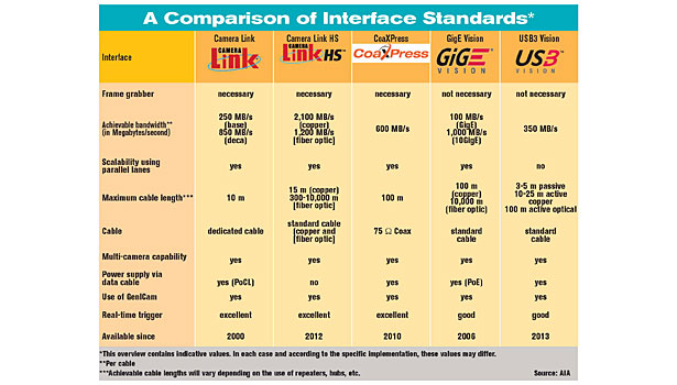
End-users have several interface standards to choose from. Camera Link, the first true machine vision interface and standard, was introduced by AIA in 2000. AIA has since introduced three more standards: GigE Vision in 2006, Camera Link HS in 2012 and USB3 Vision in 2013. The Japan Industrial Imaging Association introduced CoaXPress in 2010.
“No one standard is best for all applications,” says Doug Kurzynski, project manager for Keyence Corp. and an AIA-recognized certified vision professional—advanced. “Several criteria should be used to determine which interface standard is best for a specific application. The most important are bandwidth, cable length, if a frame grabber is needed, and the budget for the vision system.”
AIA Standards
“Camera Link brought order out of chaos,” says McCurrach. “It defines its own dedicated cable, which uses the 3M Mini D Ribbon 26-pin connector, and requires a frame grabber in an available slot in a PC.”
Designed for medium- to high-performance image acquisition, the Camera Link (CL) interface serializes 28 bits of parallel video data into four serial low-voltage differential signals (LVDS) with a parallel LVDS clock signal. Separate wire pairs in the cable are used to send trigger and high-speed control information to the camera, including a lower-speed bidirectional communication link.
In addition, CL allows the use of more than one cable per camera. Maximum length of each cable is 10 meters.
Bandwidth is 255 megabytes per second (MBps) for one cable, 850 MBps for two cables. The single cable is known as base configuration. The second cable supports a second and third serializing chip named medium and full configurations.
The CL cable is relatively bulky, somewhat inflexible and more expensive than an Ethernet or coaxial cable. In addition, CL, like Camera Link HS and CoaXPress, requires a frame grabber, which increases the cost of a vision system.
However, the frame grabber transfers image data using direct memory access channels. This allows more CPU cycles to be dedicated to the postprocessing of images.
CL was revised in 2004 (version 1.1), 2007 (1.2) and 2011 (2.0). The latest version allows for the use of mini (footprint) connectors and a smaller format 14-pin connector (PoCL-Lite). Power over Camera Link allows the camera to be powered by the frame grabber through the CL cable, saving end-users space and money.
Last year, AIA introduced Camera Link HS (CLHS), which, despite its name, is not a sequel to CL. CLHS is based on a Teledyne DALSA Inc. initiative originally called HS Link, says Eric Carey, director of research and development for Teledyne DALSA Inc. and chairman of the GigE Vision committee for AIA since 2006.
CLHS uses off-the-shelf components developed for the high-volume telecom and computing industries. The standard improves on CL by offering bidirectional low latency, low-jitter triggers, bidirectional general purpose input-output support, a high bandwidth communication channel and video data integrity with real-time data resend. CLHS also has video packetization that supports parallel image processing over multiple PCs.
CLHS offers two physical layer implementations, the M protocol and the X protocol. The M protocol offers 3 gigabits per second (Gbps) of effective bandwidth per lane. It uses CX4 cable, which can reach 15 meters and has eight lanes. One lane transfers communication from the frame grabber to the camera.
Each of the remaining seven lanes supports 300 MBps of effective bandwidth from the camera to the frame grabber, for a maximum total of 2.1 Gigabytes per second (GBps). An SFP copper or fiber optic cable, with a bandwidth of 300 MBps, can also be used. Copper cable can reach 10 meters, while fiber optic can reach 10,000 meters.
The X protocol offers 10 Gbps of effective bandwidth per lane. It uses SFP+ copper or fiber optic cable, which has two lanes. One lane transfers communication from the frame grabber to the camera. The other lane supports 1.2 GBps (1,200 MBps) of effective video bandwidth from the camera to the frame grabber.
SFP+ cable lengths are the same as the SFP cable. Fiber optic cables offer small size, low cost, noise immunity and come in flex-life-rated grades.
The GigE Vision standard is based on Gigabit Ethernet, which uses the network interface cards and RJ-45 ports already present on most PCs and laptops. GigE Vision has a bandwidth of 125 MBps. Full bandwidth can be sustained with a standard NIC card.
GigE Vision is great for a vision system that requires a long cable. The standard allows for the use of Ethernet cable (Cat-5e or Cat-6) at lengths up to 100 meters without active repeaters.
GigE Vision allows integrators to easily scale up a system with Ethernet switches and hubs, making it well suited for network applications. Also, because each GigE Vision camera uses an IP address, there is no limit to how many cameras can be operated on the same network.
The main drawback of GigE Vision is that it does not support real-time triggering. Also, installing drivers and software on the PC can be tricky. For this reason, Dirk Lipper, VisionPro product marketing manager for Cognex Corp., recommends an experienced vision-system integrator install the system.
Earlier this year, Microscan Systems Inc. introduced Visionscape 6.0, a multiplatform software that supports the GigE Vision standard. Jonathan Ludlow, machine vision promoter for Microscan Systems Inc., says integrators can use the software to easily install either a PC- or smart camera-based vision system. Integrators can develop, test and install simple or complex applications using point-and-click functionality.
Version 1.2 of GigE Vision was released in January 2010. It allowed interface control of non-streamable devices, such as input-output boxes. The standard was revised again (2.0) in late 2011 to accommodate networked video distribution applications and to formally support 10-Gbps (1.25 gigabytes) Ethernet systems. Built on Ethernet, the standard supports any physical medium of Ethernet natively.
The latest interface standard from AIA is USB3 Vision (1.0). Based on the USB 3.0 interface—also known as SuperSpeed USB—the standard uses a USB 3.0 port, which appears on many new PCs and is planned to be standard on all PCs by 2015.
USB3 Vision has a bandwidth of about 400 MBps, but that will double to 800 MBps this fall, according to the USB 3.0 Promoter Group. The organization says that, realistically, it will take about 2 years to see 10-Gbps plug-in cards being used. These cards will allow USB3 Vision to achieve Camera Link medium and full speeds without a frame grabber.
The standard allows data and power (up to 4.5 watts) to be transmitted over the same passive cable, which can be up to 5 meters long. Greater lengths are possible with in-cable or optical repeaters, or active cables.
“An active cable features specialized circuitry in the connector or the cable itself that enables it to act as a repeater,” says Carey. “This type of cable can extend the cable length of USB3 Vision to 15 to 20 meters, and do so with less signal degradation than a passive cable.”
The biggest advantage of USB3 Vision is the popularity and ease of use of the USB interface, which camera manufacturers anticipate will draw more end-users into the vision market. Another advantage of USB3 Vision is that it writes data directly to PC memory, reducing CPU processing load.
The main drawback of USB3 Vision is the short passive cable length. However, with active technology, this is minimized.
Cognex expects its VisionPro image-processing software to be USB3 Vision-compliant this year. It currently meets the CL, CLHS and GigE Vision standards.
“The release of a new standard is a positive thing for the industry and should bring down the price of vision systems,” says Lipper. “But it’s not a unique challenge for us because we update our software twice a year. We’ll do extensive testing on several USB3 cameras this year and make sure VisionPro meets the standard.”
One From Japan
CoaXPress (CXP) was introduced by the Japan Industrial Imaging Association (JIIA) in December 2010. This standard combines the simplicity of coaxial cable with high-speed serial data technology. It requires a host frame grabber.
Bandwidth is 6.25 Gbps over a single cable, and it is scalable over an unlimited amount of cables. Maximum cable length is 130 meters without any hubs or repeaters.
Because coaxial cable has the ability to carry many channels of image data and meta-data, CXP allows the use of an interface device that links many cameras together in a chain. To enhance camera control or real-time triggering, the standard has a low-speed uplink channel that operates at 20.833 Mbps.
CXP has an optional external 24-volt power supply that delivers up to 13 watts to the camera. Applications that require higher wattage must use a separate power supply.
Besides high bandwidth, the standard’s other main appeal is cost savings. It allows the use of common RG59 and RG6 coaxial cable, which is relatively inexpensive. Because this cable is prevalent in vision systems that use analog cameras, the standard enables a smooth upgrade to digital cameras.
A Method and a Module
In 2005, several years after AIA introduced CL, the European Machine Vision Association (EMVA) developed EMVA 1288. This standard defines a method that vision-system developers can use to easily compare camera and image sensor specifications and calculate system performance. It also provides rules and guidelines on how to report results and how to write device datasheets.
The standard consists of various modules. Each module builds a simple mathematical model of the parameter to be described. Next, it defines a method to acquire specific image data. Finally, it computes the parameter based on the measured data.
Since being introduced, the standard has been revised twice. Version 3.0, released in November 2010, is valid for area and linescan cameras (monochrome and color), as well as analog cameras used in conjunction with a frame grabber. Image sensors are described as part of a camera.
GenICam is an application programming interface (API) standard that brings plug-n-play capability to compliant components, says McCurrach. Administered by the EMVA, GenICam is an abbreviation for Generic Interface for Cameras.
All the camera interface standards (AIA, EMVA or JIIA) use GenICam to provide a generic way for an application to control a camera via a standardized HTML file. Using GenICam as a common module provides a similar look and feel for the end-user, independent of which standard is being used. Also, because it was developed by many machine vision companies, GenICam provides a valuable behind-the-scenes look into the standardization of camera function.
Companies that made up the EMVA API subcommittee started working on the standard in 2003. The standard’s first module, known as GenApi, was ratified in 2006. GenTL, the final module, was ratified in 2008.
GenApi uses an XML description file to configure, access and control cameras. GenTL is the transport layer interface, which enumerates the cameras, grabs images from the cameras, and moves them per the application. Standard Feature Naming Convention, the other module, recommends names and types for the common features in cameras to promote interoperability.
“GenICam is the glue of communication between cameras and hosts in a vision system,” says Ludlow. “All the interface standards define the physical connection of interoperable components. However, whereas the early standards provided an alphabet, the newer standards provide a language.”
Looking for a reprint of this article?
From high-res PDFs to custom plaques, order your copy today!


