Machine Operator Safety 101
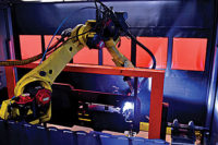
Bigger, faster machines aren?t always better. In fact, automated equipment is only as good as it is safe. Industrial robots, screwdrivers, welders, punch presses, conveyors and other assembly equipment can pose numerous hazards.
Collars, couplings, cams, clutches, flywheels, shaft ends, spindles, meshing gears, and horizontal or vertical shafting are some examples of common rotating mechanisms that may be hazardous to machine operators or maintenance personnel.
Safeguards are essential for protecting operators from needless and preventable workplace injuries. They prevent fingers, hands, arms and any other body parts from making contact with the moving parts of a machine.
Manufacturing engineers must ensure that safeguards are implemented correctly and work as intended. A good safeguarding system eliminates the possibility of an operator coming in unintended contact with any type of automated equipment.
Fortunately, safety standards exist to guide engineers and ensure that assembly lines are safe. The most up-to-date standard is ANSI/RIA R15.06, the American National Standard for Industrial Robots and Robot SystemsSafety Requirements. It was issued in 1999 by the American National Standards Institute (Washington, DC) and the Robotic Industries Association (Ann Arbor, MI).
Hazards inherent in production machinery should be identified during safety studies conducted at the design stage. This identification process is called risk assessment.
The ANSI/RIA R15.06 standard addresses risk estimation, risk reduction determination, safeguard selection and selection validation. It instructs engineers to examine every task of the machine and to identify all possible hazards that may be related to each given task.
A machine task can have multiple hazards associated with it. For each task-hazard combination, engineers should evaluate the danger to the machine operator. Severity of the resultant injury, the amount of exposure to the hazard, and the ability for the operator to avoid the hazard must be considered.
Risk Reduction
Risk reduction categories determine the type and level of safeguarding that is required. Risk reduction categories are R1, R2, R3 and R4. The most dangerous category is classified as R1. It requires a "control reliable" safety system and either hazard elimination or substitution based upon the operator?s exposure.Safety systems and circuitry must be designed for control reliability. Any component failure should not prevent the nor-mal stopping action of the machine. This is achieved through a dual channel control system with a monitoring function. The circuit also has an interlock function and the ability to self-check.
If a control reliable safety system experiences a detectable fault, it will immediately shut down the dangerous aspects of the machine. If the safety system does not detect a fault, it will still stop the machine if an unsafe condition is detected.
The self-checking or monitoring function of the safety control circuitry prevents a successive machine cycle from occurring under a fault condition. An operator will not be allowed to run the machine unless the safety circuit is in complete working order.
In a control reliable safety system, the self-checking function of the circuit occurs on system start up and at each demand of safety from the machine operator. Control reliable circuit performance is required in safety systems that protect against hazards that could result in serious injuries.
Safety Rated Relays
Under the provisions of ANSI B11.1990?5.5.1, redundant safety systems that require the use of relays must use devices that have a positive relationship between the normally open (NO) contacts and the normally closed (NC) contacts.With these force-guided safety contacts, if at least one normally open contact becomes welded, when the coil is de-energized, all normally closed contacts maintain a gap of at least 0.5 millimeter or greater. Even if a normally closed contact is welded, all normally open contacts maintain a gap of at least 0.5 millimeter in the coil-energized mode. This is in accordance with the European Norm safety standard EN50205.
Predictable performance of hardware under fault conditions is one way to reliably design safety circuits. An interlock dual channel safety system ensures that under a fault condition the safety circuit goes into a lock-out condition until the fault is cleared or corrected.
Risk reduction category R2 demands that engineering controls be implemented to prevent operator access to the hazard or requires a stopping of the hazard before operator exposure. It has a provision within it called R2B, which describes a "Single Channel With Monitoring" circuit performance.
Generally, single channel with monitoring circuitry is used to protect personnel from hazards that might result in slight injuries. Those injuries do not require hospitalization and can be cured through in-house first-aid kits.
Safety circuits must be hardware-based and include components that have been safety rated. They should also be checked at suitable intervals, such as machine start-up and on each demand of the safety function.
After risk assessment and risk reduction have been evaluated, it?s time to choose a safeguard. A wide variety of protective devices can be used to safeguard equipment, such as safety mats, emergency-stop buttons, safety door interlock switches and safety light curtains. Basic safeguards include protective barriers and warning signs.
Safety Mats
In some industrial environments, safety mats may be a good solution. Safety mats are pressure-sensing floor coverings that typically use two conductive plates separated by a nonconductive compressible insulator. The two conductive plates contact each other when a specified pressure is applied to the separator.Safety mats use minimum weight and size requirements to standardize mat behavior. They are typically used in conjunction with other safety devices or protective measures.
Safety mats offer numerous benefits. For instance, because they do not obstruct the operator, safety mats don?t slow down operator cycle Arial. Also, they offer protection for multiple machine operators. If one operator is inside a hazardous area, another operator will not be able to restart a machine because the safety mat overrides the machine actuators. And, due to the various shapes and sizes of safety mats, they can be placed side by side, linked up together for a complete safety grid with no dead or nondetection areas.
E-stop Circuits
Emergency stop circuits (e-stops) are one of the most common safety systems. They should be located within reach of any position where an operator is exposed to a machine pinch point. E-stop circuitry must be fully compliant with the NFPA 79 code, which requires the override of all machine functions and causes all moving parts to stop by removing drive power from the actuators of the machine.E-stop pushbuttons are bright red with a yellow background. The pushbutton shape should be a palm or mushroom-head type. The e-stop button itself must be the manual reset variety. It should be installed so that resetting the button will not initiate a restart of the machine. The restart must be achieved through an independent start button located outside the hazardous area.
The typical e-stop pushbutton has two redundant safety outputs that feed into a safety relay unit with force-guided relays. The relay unit performs an interlock function that ensures that successive demands upon the safety circuit are not continued under fault conditions.
A safety relay unit has multiple safety outputs that shut down safety contactors that are wired in series. They shut off power to the machine. The circuit features a feedback loop wired through the external contacts of the safety contactor into the safety relay unit?s third input channel. This is commonly known as the safety circuit?s monitoring channel. The start-restart button is wired in series with the feedback loop.
Interlock Switches
Safety door interlock switches physically monitor the position of hard barriers. They are a very popular safety measure used for detecting the position of hard guards.The hard guard is affixed with a special tamper-proof actuation key while the safety door interlock switch features the mating insertion head. Some safety door interlock switches feature a solenoid. Safety door interlock switches feature positive opening internal mechanisms that ensure switch contacts open whenever the safety switch is actuated.
Safety standards require that physical barriers be constructed to withstand the operational and environmental conditions of the machine. Also, they must be free of sharp edges and projections so that they do not create an additional hazard. Safety door interlock switches must have a plug or key that cannot be easily duplicated. They should be tamper resistant.
However, safety door interlock switches require additional time for the operator to open and shut the door. In repetitive operations, this could potentially add up to a lot of wasted time.
Two-Hand Controls
Two-hand control systems ensure that an operator?s hands are occupied during hazardous machine cycles. Safety standards require that two-hand control systems be designed to prevent accidental or unintentional operation of the machine. Also, the operator?s hand controls must be arranged by construction or separation to require the use of both hands within 500 milliseconds (0.5 second) to cycle the system.In addition, the system must be designed to require the release of the operator?s hand controls and a reactivation of the operator?s hand controls before an additional machine cycle can be initiated. A stopping operation must also be issued if one or both of the operator?s hands are removed from the controls during the hazardous portion of the machine cycle.
Two-hand control systems typically increase the machine cycle and operator inaction time. As a result, these systems often lead to a stronger urge for operator circumvention in order to achieve higher throughput.
Light Curtains
Safety light curtains are the most popular method of machine safeguarding. They use photo-eye technology and reliable internal circuitry to provide the utmost in safety protection. Safety standards dictate that light curtains must only be of the through-beam variety, which means that light curtains are available in emitter-receiver pairs.A light curtain monitors access to the machine¿s internal and hazardous area. As long as an operator is reaching into the machine through an area monitored by a light curtain, the ma-chine will act as if an e-stop has been initiated. Light curtains are commonly used in a "restart" interlock mode, which means once the light beams have been broken, a lock out is initiated and the machine cannot be restarted until all obstructions have been removed from the sensing area. The machine start button is located out of the hazardous area for machine restart.
Safety light curtains must be labeled with maximum response time and maximum angle of the emitter beam pattern. Also, protective height and minimum object sensitivity must be labeled. Response Arial are a factor in determining how close the light curtain can be placed to the point of hazard.
Light curtains come in two varieties: Type 4 and Type 2. Type 4 light curtains are used in control reliable safety systems. These devices feature dual redundant microprocessors and, typically, a provision for monitoring the condition of the safety contactor¿s auxiliary contacts. Typically, Type 4 light curtains are used to protect personnel from hazards that can result in serious injuries.
Type 2 light curtains are used in single channel with monitoring safety systems. They feature one microprocessor, two safety outputs and a provision for monitoring the condition of the auxiliary contacts.
After any safeguards have been put in place, the task-hazard combinations must undergo the risk assessment process again and must be re-evaluated for residual risk. If the remaining risk is at tolerable levels, the risk assessment process comes to an end.
Tolerable risk is the amount of risk that a normal person is said to accept. This concept is quantified in the safety standards and is a combination of the type of injury, time of exposure and possibility for avoidance of any given hazard.
Looking for a reprint of this article?
From high-res PDFs to custom plaques, order your copy today!


