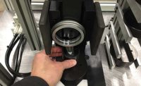
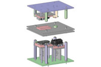
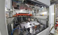
Both hot-plate welding and infrared welding are used to assemble plastic parts. In hot-plate welding, the tooling contacts the parts. In infrared welding, it does not.
Both technologies have recently benefited from significant process advancements, and both are growing in popularity. Precise control of tooling position, velocity, force and acceleration are improvements that provide a new level of control and process data acquisition. Additionally, with the offering of smaller and more efficient machines, engineers have more practical options for consideration.
Infrared welding has been a viable joining method for some time, although it has only recently gained popularity in the United States. The noncontact premise of this method addresses a significant challenge of hot-plate welding—preventing plastic from sticking to the surface of the heated platen. However, that benefit is negated to some degree with other, less desirable characteristics.
Both processes are commonly used for assemblies that require high strength or a hermetic seal. They can also be used effectively to join parts with large, complex geometries when other joining methods are not practical. Additionally, these joining methods are excellent for sealing internal walls and cavities.
Hot-Plate vs. Infrared
There are three primary ways to transfer heat for plastics joining: conduction, convection and radiation. The principal heat transfer method for hot-plate welding is conduction, while the primary method with infrared welding is radiation.
The hot-plate welding process consists of three key steps: the melt phase, the open phase and the seal phase.
The sequence of operations takes place this way: An operator (or automated machinery) loads the components to be welded into opposing press platens. At cycle start, the machine positions a heated platen between the two press platens. The machine then positions the press platens so that molded weld ribs on each component just touch the heated platen. This is the melt phase.
Next, the machine retracts the press platens, removing the components from the heated platen. The machine then retracts the heated platen. This is the open phase.
During the seal phase, the machine activates the press platens to push the two semi-molten ribs on each component against each other to form the actual weld. When the plastic has cooled and resolidified, the joined components are unloaded from the tooling.
The infrared welding cycle is similar. It includes the same fundamental steps as hot-plate welding. The one big difference is that there is no contact between the plastic components and infrared emitters on the heated platen during the melt phase.
Hot-Plate Heating Theory
Conduction is the primary method of heat transfer in hot-plate welding. Heat conducts from the heated platen directly to the weld rib. From the part surface, it continues to conduct and ‘soak’ deeper into the rib. An appropriate amount of heat soak into the weld rib is crucial for achieving high-bond strength and a tight, hermetic seal. The goal is to optimize the heat soak time. This will help ensure that when the two heated components are brought together in the seal phase, there is an optimal depth of heat-softened material on the two opposing surfaces.
This combined depth is called the heat-affected zone (HAZ), and it can actually be measured under magnification. If the HAZ is too small, it means that excessive displacement of the semi-molten material has taken place and the likely result is a weak weld with poor sealing performance. If the HAZ is too large, then it’s likely that insufficient pressure was applied during the seal phase, and the weld will be poor.
Infrared Heating Theory
Infrared heating of the weld rib surface is achieved through radiation. The infrared source emits light waves of energy that are absorbed at the surface by the components. Conduction within the plastic itself now spreads the heat throughout the rib.
A critical parameter is the rate of heating. Thermoplastic materials melt and reflow when they are heated. If they are heated too quickly, there is a risk of material degradation, burning or charring. Many resins absorb the initial infrared energy rapidly, but most of them do not conduct that surface heating very quickly. Yet, just as it is with hot-plate welding, it is still necessary to achieve a sufficient depth of heating into the weld rib to execute a robust welding process.
The rate at which a material absorbs infrared radiant heat is characterized by three properties: absorptivity, transmissivity and reflectivity. These material properties are affected by the material type, color, fillers and other factors. Additionally, the emissivity of the infrared emitter (its ability to emit radiation) also contributes to the effectiveness of radiant heat transfer and affects the rate of heating.
The density of the infrared light as it reaches the surface being heated affects the rate of heating, as well. This density is affected by the distance between the emitter and the heated surface and by how the infrared energy is focused.
In short, there are many factors that affect how quickly a plastic will absorb infrared energy. The key is to control this rate of heating to avoid material degradation. For example, an opaque, black material with a high percentage of glass filler will absorb radiant energy at a very high rate, but it will not conduct that surface heating as aggressively. As a result, the outer surface might be susceptible to overheating. On the other side of the spectrum, a white material with no filler might conduct the surface heating more efficiently, but it will not absorb the initial infrared energy quickly. It will not be at much risk for overheating, but the overall cycle time will likely be longer.
Material Displacement Comparison
Another big difference between hot-plate welding and infrared welding is the displacement of material during the welding cycle. For this discussion, displacement is defined as any material that is moved from its original location at the melt rib to another location (flash).
In hot-plate welding, there is physical contact between the heated platen and the weld rib on the plastic components. As a result, there is displacement of the molded weld rib. As the press tooling brings the weld rib surfaces into intimate contact with the heated tooling, the material is displaced—this is a good thing. During this process, the weld ribs conform to the heated tool surfaces, which should be accurately machined to match the part. This assures that the weld rib surfaces are formed precisely to design while they are being sufficiently heated.
During the melt cycle, this displacement is occurring on both components simultaneously, creating matched weld rib surfaces. This precise contact and related material displacement is a significant element of the hot-plate welding process, since it prevents some issues associated with typical molding inconsistencies. Because the surfaces are uniform with each other, when welding pressure is applied in the seal phase, it is evenly applied along the entire length of the weld rib. Balanced welding pressure is imperative in creating high-strength, tightly sealed welds while displacing minimal material.
With infrared welding, there is no contact between the weld rib and the infrared emitters. Therefore, there is no controlled material displacement to correct inconsistencies in the weld ribs. For this reason, it is important that the dimensions of the two molded components are precisely controlled during molding to achieve “as-designed” surfaces.
When assembling contoured weld rib surfaces with the infrared welding process, the placement and distance of the infrared emitters from the weld rib surface becomes particularly critical. To ensure even heating and ultimately a robust process with minimal plastic displacement, the tool design must be critically assessed and proven to heat the contoured surfaces evenly. If uneven heating occurs during the melt phase, there will likely be an uneven application of pressure through the weld joint during the seal phase. This could result in poor weld quality.
Sensitive Internal Components
Product designers can cleverly secure subassemblies and internal devices within the components to be welded. Whether these internal devices are batteries, PCBs, valves, filters, O-rings or LED lights, engineers should take care that the energy from the welding process will not damage them.
In hot-plate welding, the duration of exposure to the heated platen is quite limited, but the proximity of the heat source to the subassemblies requires evaluation. Infrared welding exposes subassemblies to high-energy radiation for an extended period. This exposure could be problematic and damaging to those parts. Tools that mask or shield vulnerable subassemblies from the infrared energy may be required.
With either method, simulating the heat energy and exposure duration should be relatively easy to perform, and this testing is highly recommended.
Heated Tooling Challenges
Infrared welding completely eliminates the challenges of heated tool wear, plastic sticking to the heated tool, and resin build-up on the heated tool. The absence of contact between the infrared emitters and the weld ribs removes the possibility that semi-molten plastic will wear, stick to, or build up on the tooling.
Advancements in durable, anti-stick coatings have greatly reduced much of this issue for hot-plate welding. But, even with high-performance materials and coatings, the tool coatings must be considered an item that requires service and maintenance.
The advent of servo-controlled press platens in hot-plate welding has also helped with the sticking issue. With servo control, the press platens can withdraw the components from the heated platen at a high rate of acceleration. This minimizes or eliminates material sticking and build-up on the heated platen during the melt phase.
Cost Comparisons
In addition to the processing differences between the two technologies, there are operating and maintenance cost differences as well.
Infrared welding machines draw a large amount of power during the melt phase. However, the infrared emitters are switched off through the rest of the process. As a result, the machine draws less power overall. Hot-plate welding draws a higher amount of power, because the heated platen must be maintained at the programmed temperature throughout production. In addition, platen preheating is required at the outset of the production shift.
Cycle time is significantly longer with infrared welding, due to the rate at which the materials can absorb radiation and their ability to conduct that heat deep into the weld rib. Typical cycle times for infrared welding vary from 20 to 60 seconds. On the other hand, hot-plate welding cycle times can be significantly shorter due to the speed and efficiency of conduction heat transfer. Typical cycle times for hot-plate welding vary from 8 to 30 seconds.
Capital equipment costs of the two processes are reasonably comparable. Depending on the style of emitters used, the tooling for infrared welding equipment can be more expensive—possibly as much as 30 to 40 percent more than hot-plate welding. However, this is highly application dependent. Both the size and geometry of the tooling are factors.
As for maintenance, infrared emitters must be replaced every few years in a typical installation, and they can be quite expensive, even for standard emitters. Custom emitters cost even more. What’s more, they may require a long lead time to replace, necessitating the inventory of expensive spares.
The cartridge heaters used in hot-plate welding also require replacement, but they are much more robust and less expensive than infrared emitters. The life and durability of the non-stick coatings on the heated platen is finite, and these tools must be stripped and recoated occasionally. If the heated platen is custom or prone to high wear, engineers would be wise to secure back up tooling.
A Winner?
Infrared welding and hot-plate welding are both viable, robust processes with certain advantages and disadvantages. As with all plastics joining challenges, it is the application’s unique characteristics and requirements that should drive the process selection. We strongly encourage companies to work with equipment suppliers that have proper testing and experienced application lab capabilities to produce relevant welded samples for evaluation. When selecting a process, the key elements of strength, flash control, cycle time and overall production robustness must be assessed. The results should point to one welding process over the other.
For more information on plastics joining technology, call 800-324-6205, email sales@extolinc.com, or visit www.extolinc.com.


